AK-CH 650 Capacity controller RS8ER302 © Danfoss 2016-02 63
5. Conguration of Analog
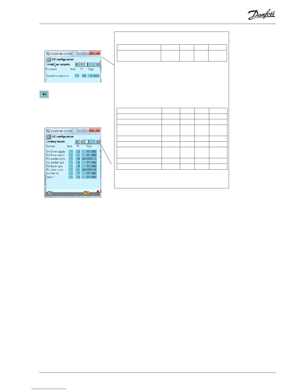
outputs
Press the +-button to go on to
the next page
6. Conguration of Analog
Input signals
Conguration - continued
Function Output Module Point Type
Speed control of compres-
sor
AO1 1 24 0-10 V
We set up the analog outputs for control of the compressor speed.
We set up the analog inputs for the sensors.
5 - Analog outputs
The possible signals are the
following:
0 -10 V
2 – 10 V
0 -5 V
1 – 5V
Select for:
• Speed control comp.
• Speed control fans.
• Show cutin compressor
capacity
6 - Analog inputs
The possible signals are the
following:
Temperature sensors:
• Pt1000
• PTC 1000
Pressure transmitters:
• AKS 32, -1 – 6 bar
• AKS 32R, -1 – 6 Bar
• AKS 32, - 1 – 9 Bar
• AKS 32R, -1 – 9 Bar
• AKS 32, - 1 – 12 Bar
• AKS 32R, -1 – 12 Bar
• AKS 32, - 1 – 20 Bar
• AKS 32R, -1 – 20 Bar
• AKS 32, - 1 – 34 Bar
• AKS 32R, -1 – 34 Bar
• AKS 32, - 1 – 50 Bar
• AKS 32R, -1 – 50 Bar
• AKS 2050, -1 – 59 Bar
• AKS 2050, -1 – 99 Bar
• AKS 2050, -1 – 159 Bar
• User dened (only ratio-
metric, min. and max value
of the pressure range must
be set)
Voltage signals for refer-
ence displacement:
• 0 – 5 V,
• 0 -10 V
S4 Brine supply
S3 Brine return
P0 suction pressure
Ss suction gas
Sd disch gas
Pc cond. press.
S7 warm brine
Sc3 air on
Ext. Ref. Signal
Heat recovery
Saux 1 - 4
Paux 1 - 3
Voltage input 1 - 5
• 0 -5 V,
• 0 -10 V,
• 1 – 5 V,
• 2 – 10 V
Sensor Input Module Point Type
Brine return temp. S3 AI1 1 1 Pt 1000
Brine supply temp. S4 AI2 1 2 Pt 1000
Thermostat sensor in plant
room - Saux1
AI5 1 5 Pt 1000
Outdoor temp. - Sc3 AI7 1 7 Pt 1000
Disch. gas temperature - Sd AI8 1 8 Pt 1000
Suction gas temperature
- Ss
AI9 1 9 Pt 1000
Suction pressure - Po AI10 1 10 AKS32-12
Condenser pressure - Pc AI11 1 11 AKS32-34