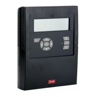
AK-LM 330 RS8FR302 © Danfoss 2015-08 57
12. Move on with the settings for voltage signal 1
!
13. Repeat settings for the other voltage signals
14. Select Digital inputs
15. Overview for Digital inputs
16. Move on with the settings for Digital input 1
!
!
When this function is set to 'YES', a relay will be reserved which couples
with the voltage signal. Denition of the connection point must be done
during the I/O conguration.
(In our example, the setting is NO in Voltage Signal 1 and YES in Voltage
Signal 2).
Scaled values
Min. reading is the value that will be presented when the input signal is
at its minimum, e.g. 0 V.
Max. reading is the value that will be presented when the input signal is
at its maximum, e.g. 10 V.
Cut-in and cut-out values and alarm settings refer to the scaled values.
!
When this function is set to 'YES', a relay will be reserved which couples
with the digital input signal. Denition of the connection point must be
done during the I/O conguration.
(In our example, no relays are connected to any of the signals).
The status of the alarm is shown on the 'current alarm status' line. This
status display is delayed with 'alarm delay' for the input signal.
Signal history
The level of the input is continuously recorded so that the following can
be read:
• On time in % for the last 24 hours
• Total On time in hours
• Number of changes to On in the last 24 hours
• Total number of changes to On
The 'Status' eld shows the status of the input signal.
Check of settings - contiuned
 Loading...