3.7 Installation instructions
Status LED / B&L:
GREEN is power on.
– flashing if maintenance needed
YELLOW is an indicator of Error.
– the sensor head is disconnected or not the
expected type
– AO configured as 0 – 20 mA, but no current
is running
– flashing when sensor is in special mode (e.g.
when changing parameters with the Service
Tool)
– Supply voltage out of range
RED flashing: is an indication of alarm due to gas
concentration level. The Buzzer & Light behaves
identical to the status LED.
Ackn. / Test button / DI_01:
TEST: The button must be pressed for 8 sec.
– Critical and warning alarm is simulated and
AO goes to max. (10 V/20 mA), stops on
release.
ACKN: If pressed during critical alarm, as default*
the relays and Buzzer go out of alarm condition
and back on after 5 minutes if the alarm situation
is still active.
* the duration and whether to include the relay
status with this function or not is user defined.
DI_01 (terminals 1 and 2) is a dry-contact
(potential-free) behaving identically to the
Ackn./Test button.
DC supply for external Strobe & Horn
Whether the DGS is powered by 24 V DC or 24
V AC, a 24 V DC power supply (max. 50 mA)
is available between terminals 1 and 5 on
connector x1.
Jumpers
* JP4 open → 19200 Baud
JP4 closed → 38400 Baud (default)
* JP5 open → AO 0 – 20 mA
JP5 closed → AO 0 – 10 V (default)
Note: the DGS must be power cycled before any
change to JP4 takes effect.
Analog Output:
If the analog output AO_01 is used (terminals 4
and 5) then you need the same ground potential
for the AO and the connected device.
Note: JP1, JP2 and JP3 are not used.
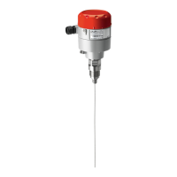
The DGS is available with one or two sensors and
B&L (Buzzer and Light) as option (see fig. 1).
For sensors that can be poisoned by e.g. silicones
like all semiconductor and catalytic bead sensors,
it is imperative to only remove the protective cap
after all silicones are dry, and then energize the
device.
The sensor protection cap must be removed
before taking the DGS into operation
Mounting and wiring
To wall mount the DGS, unscrew the lid by
releasing the four plastic screws in each corner
and remove the lid. Mount the DGS base to the
wall by fitting screws through the holes which
the lid screws were fastened by. Complete the
mounting by re-applying the lid and fastening
the screws.
The sensor head must always be mounted so that
it points downwards. The DGS-IR sensor head is
sensitive to shock – special attention should be
paid to protect the sensor head from shocks
during installation and operation.
Observe the recommended placing of the sensor
head as stated on page 1.
Extra cable glands are added by following the
instruction in fig. 2.
The exact position of the terminals for the
sensors, alarm relays, digital input and analogue
output is shown in the connection diagrams (see
fig. 3).
The technical requirements and regulations
for wiring, electrical security, as well as project
specific and environmental requirements and
regulations must be met.
Configuration
For convenient commissioning, the DGS is pre-
configured and parameterized with factory-set
defaults. See Menu Survey on page 5.
Jumpers are used to change the analogue output
type and the MODBUS baud rate. See fig. 3.
For DGS with Buzzer & Light, alarm actions are
given according to following table below.
System integration
To integrate the DGS with a Danfoss system
manager or general BMS system, set the
MODBUS address using the DGS Service Tool,
using password "1234" when prompted. See the
DGS User Guide for details on operating the DGS
Service Tool.
The Baud Rate is adjusted by jumper JP4. As
default, the setting is 38.4k Baud. For integration
with AK-SM 720/350 change the setting to 19.2k
Baud.
For more information about data communication
see Danfoss document RC8AC--
Sensor replacement
The sensor is connected to the DGS via a plug
connection enabling simple sensor exchange
instead of an on-site calibration.
The internal replacement routine recognizes
the exchanging process and the exchanged
sensor and re-starts the measurement mode
automatically.
The internal replacement routine also examines
the sensor for actual type of gas and actual
measuring range. If the data does not match the
existing configuration, the built-in status LED
indicates an error. If everything is OK the LED will
light up green.
As an alternative, the on-site calibration via the
DGS Service Tool can be performed with the
integrated, user friendly calibration routine.
See the DGS User Guide for details on operating
the DGS Service Tool.
User Guide | Danfoss Gas sensor, type DGS
© Danfoss | Climate Solutions | 2022.01 BC291049702513en-000201 | 5