3.8 Installation Test As DGS is a digital device with self-monitoring,
all internal errors are visible via the LED and
MODBUS alarm messages.
All other error sources often have their origins in
other parts of the installation.
For fast and comfortable installation test we
recommend proceeding as follows.
Optical Check
Right cable type used.
Correct mounting height according to definition
in the section about mounting.
LED status – see DGS trouble shooting.
Functional test (for initial operation and
maintenance)
Functional test is done by pressing the test
button for more than 8 seconds and observing
that all connected outputs (Buzzer, LED, Relay
connected devices) are working properly. After
deactivation all outputs must automatically
return to their initial position.
Zero-point test (if prescribed by local
regulations)
Zero-point test with fresh outdoor air.
A potential zero offset can be read out by use of
the Service Tool.
Trip test with reference gas (if prescribed by
local regulations)
The sensor is gassed with reference gas (for this
you need a gas bottle with pressure regulator
and a calibration adapter).
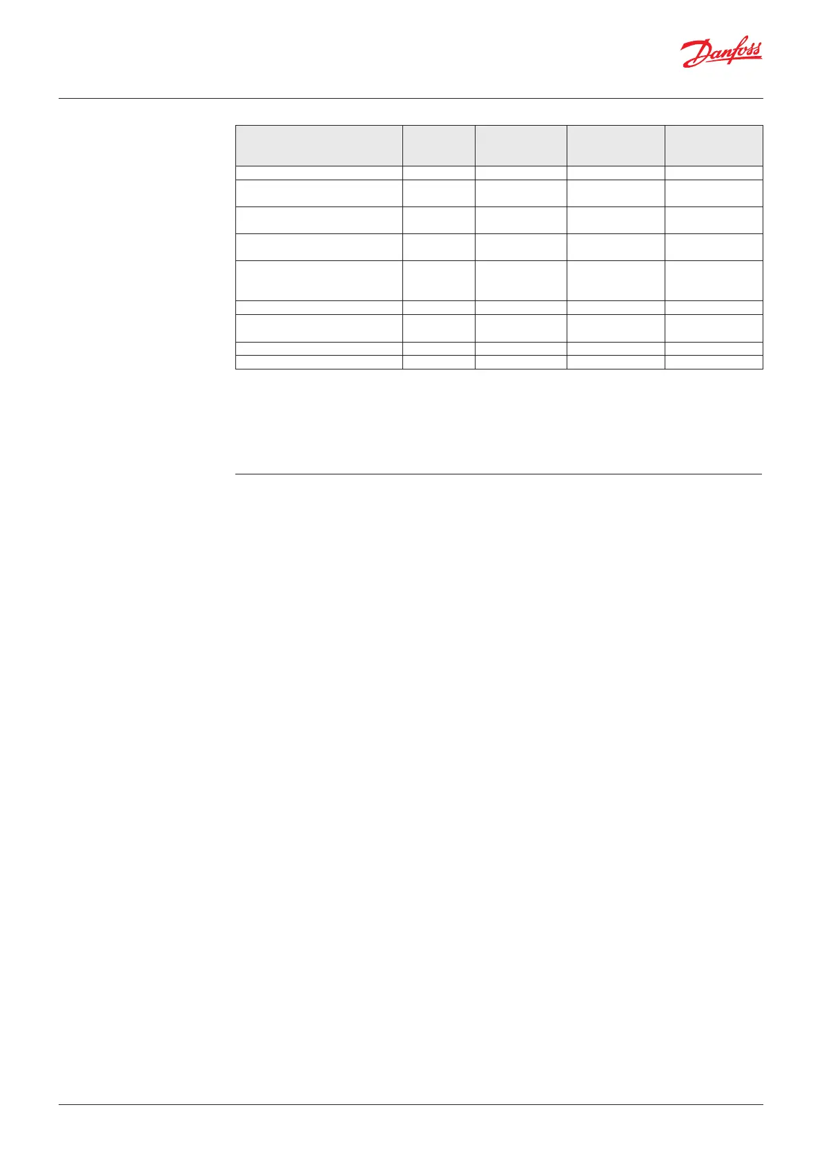
Action Reaction
Buzzer
Reaction
Light
Warning relay 1**
SPDT NO
(Normally Open)
Critical relay 3**
SPDT NC
(Normally closed)
Loss of power to DGS OFF OFF X (closed)
Gas signal < warning alarm
threshold
OFF GREEN
Gas signal > warning alarm
threshold
OFF RED Slow flashing X (closed)
Gas signal > critical alarm
threshold
ON RED Fast flashing X (closed) X (closed)
Gas signal ≥ critical alarm
threshold, but ackn. button
pressed
OFF
(ON after
delay)
RED Fast flashing X (closed)* (open)*
No alarm, no fault OFF GREEN
No fault, but maintenance due OFF GREEN Slow
flashing
Sensor communication error OFF YELLOW
DGS in special mode OFF YELLOW flashing
Alarm thresholds can have the same value, therefore both the relays and the Buzzer and Light can be triggered
simultaneously.
The alarm thresholds have a hysteresis of app. 5%
* whether to include the relay status with the acknowledge function or not is user defined.
** If the DGS has two sensors and the "Room Mode" is configured to "2 rooms", then relay 1 acts as a critical
relay for sensor 1 and relay 3 acts as a critical relay for sensor 2. Both relays are SPDT NC. The Buzzer and Light
operation is independent of the "Room Mode" setting.
In doing so, the set alarm thresholds are
exceeded, and all output functions are activated.
It is necessary to check if the connected output
functions are working correctly (e.g. the horn
sounds, the fan switches on, devices shut down).
By pressing the push-button on the horn, the
horn acknowledgement must be checked. After
removal of the reference gas, all outputs must
automatically return to their initial position.
Other than the trip testing, it is also possible to
perform a functional test by means of calibration.
For further information, please refer to the User
Guide.
Comparing sensor gas type with DGS
specification
The replacement sensor specification must match
the DGS specification.
The DGS software automatically reads the
specification of the connected sensor and
compares with the DGS specification.
This feature increases the user and operating
security.
New sensors are always delivered factory-
calibrated by Danfoss. This is documented by the
calibration label indicating date and calibration
gas. A re-calibration is not necessary during
commissioning if the device is still in its original
packaging (including air-tight protection by
the red protective cap) and if the calibration
certificate has not expired
User Guide | Danfoss Gas sensor, type DGS
6 | BC291049702513en-000201 © Danfoss | Climate Solutions | 2022.01
 Loading...