4. Operation The configuration and service is made via the hand-held Service Tool or in combination with the
MODBUS interface.
Security is provided via password protection against unauthorized intervention.
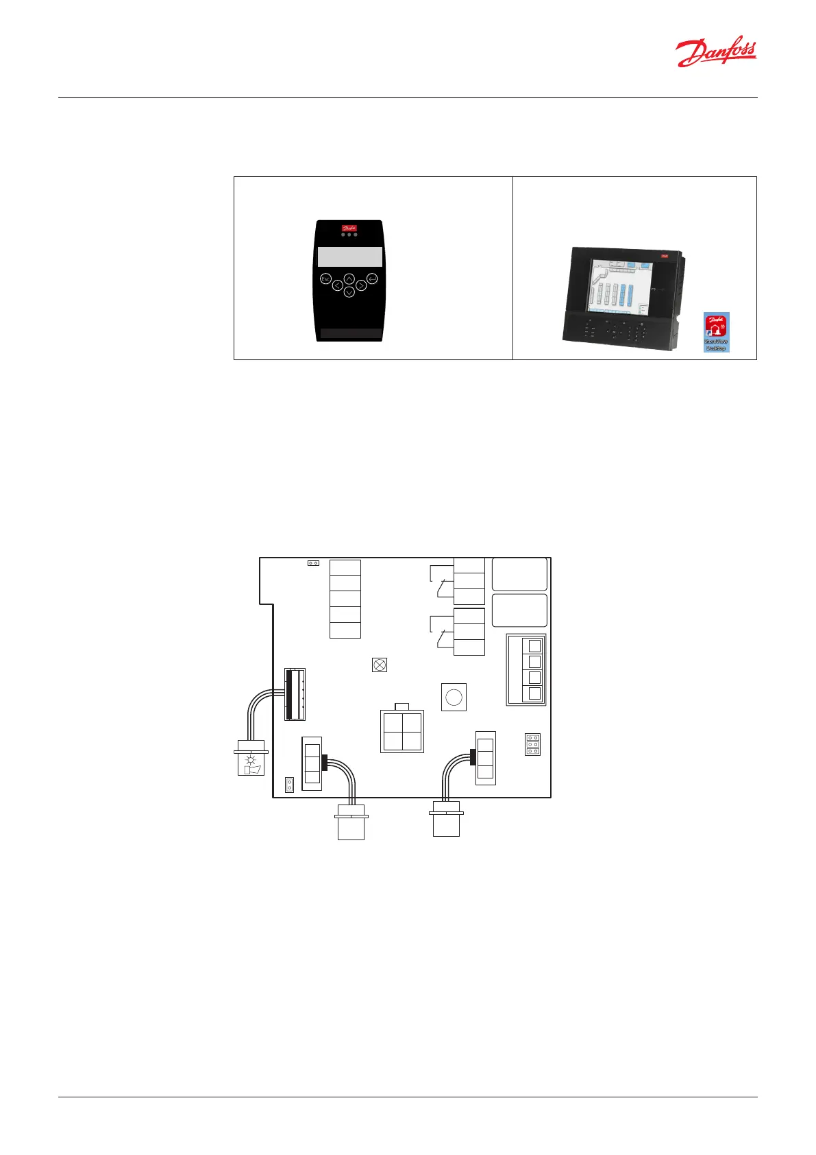
Hand-held Service Tool:
Operation is done via 6 buttons.
AK- System Manager:
The configuration is done via the graphical
display and buttons or via the PC tools
StoreView Desktop or AK-ST 500.
Gas D etect ion S ervice T oo l
Esc
←─
D1 R744 ppm
Warm-up Time
DGS Service Tool
Operation with the hand-held Service Tool is described in sections 4.1 – 4.3 and chapter 5. Operation
with the Danfoss Front End is described in chapter 6.
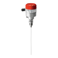
Two functions are configured via jumpers on the DGS.
Jumper 4, JP 4, located at the bottom left, is used to configure the MODBUS baud rate. As default the
baud rate is 38400 Baud. By removing the jumper, the baud rate is changed to 19200 Baud. Removing
the jumper is required for integrating with Danfoss System Managers AK-SM 720 and AK-SM 350.
Jumper 5, JP5, located at the top left, is used to configure the analogue output type.
As default this is voltage output. By removing the jumper, this is changed to current output.
Note: the DGS must be power cycled before any change to JP4 takes effect. JP1, JP2 and JP3 are not used.
JP5
5
4
2
1
not used
GND
AO_01
DI_01
S&H supply
x1
open: 0-20mA
closed: 0-10V
LED
Yellow/Green/Red
1
2
3
1
2
3
x6
x5
Rel. 3
Rel. 1
x4
4
3
2
1
not used
JP3
JP2
JP1
x3
Ackn.-/Test
button
Sensor 1
Sensor 2
Tool
x9
x2
x8
B&L
JP4
Danfoss
80Z790.1
open: 19200 Baud
closed: 38400 Baud
B-
MODBUS
A+
-
24 V AC/D
+
(critical)
(warning)
User Guide | Danfoss Gas sensor, type DGS
© Danfoss | Climate Solutions | 2022.01 BC291049702513en-000201 | 9