BC-HM VI.72.M4.02 Danfoss 11/97 5
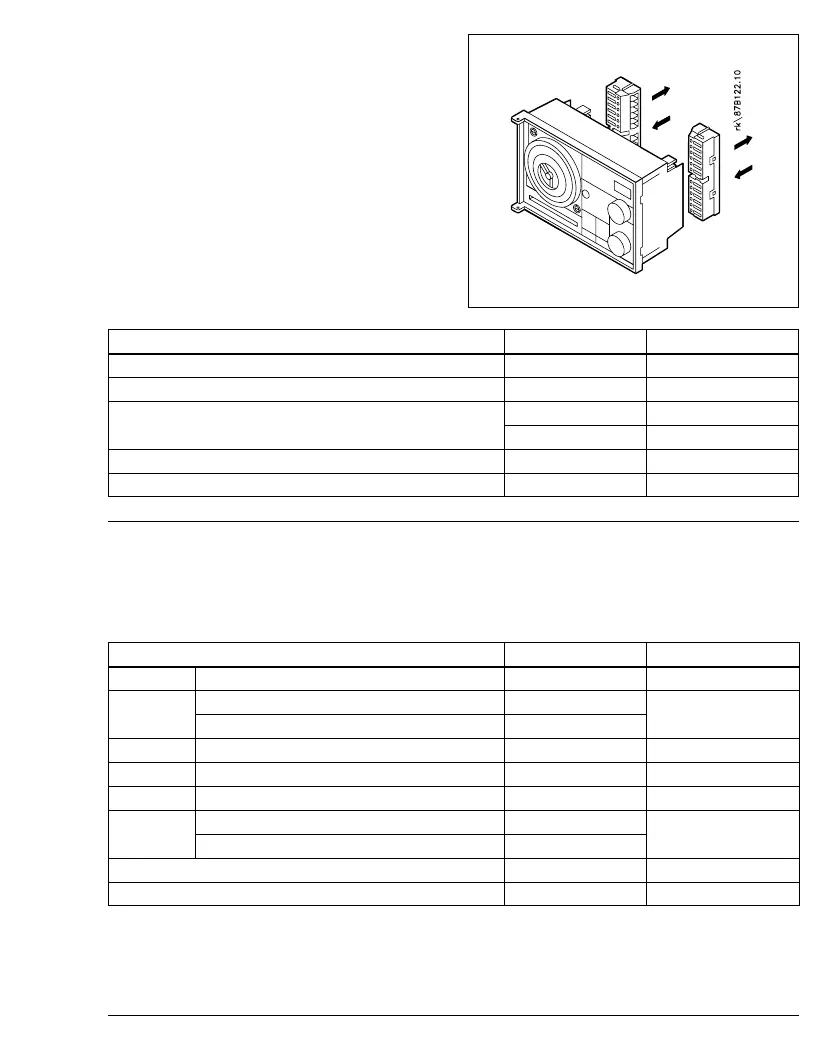
Electrical connections and
wiring diagram
Connection to 230 VAC -
(terminals 13-24)
The control must be connected using the
terminal strips with screw terminals.
Up to 3 x 1.5 mm² or corresponding
wires can be connected in each
terminal. The terminal strips are coded
to prevent terminal strips with mains
voltage being connected to sensor
terminals.
Terminal Load
Neutral (N) - 230 V~ 13
Phase (L) - 230 V~ 14
16 (close) 8(2)A 250V~
Reversible gear motor 230 V~, AMB, AMV etc.
17 (open) 8(2)A 250V~
Relay output R1 - 230 V~ (NC) 21 - 22 8(2)A 250V~
Relay output R2 - 230 V~ (NC) 23 - 24 8(2)A 250V~
Connections for sensors, etc. -
safety voltage (terminals 1 - 12)
Sensor mounting is described in the
instructions enclosed with the product.
Wire cross-section: min. 0.4 mm²
Total length of all sensor and BUS
wires: max. 150 metres.
Type Terminal
S1 flow/duct (PI circuit) ESMA/B/C/U 10 - 11
storage tank upper sensor ESMB/U
S2 7 - 9
room sensor (P circuit) ESMR
S3 frost protection sensor ESMB/U/T 11 - 12
S4 return temperature sensor ESMA/B/C/U 4 - 6
S5 external setpoint ESME 4 - 5
storage tank lower sensor ESMB/U
S6 8 - 9
compensation sensor ESMR/T
External time switch/override ECA 9010 3 - 4
Communication BUS 1 - 2
Note!
Wire resistance can give measurement
error. A resistance of 4 ohm
corresponds to a temperature increase
of about 1 degree.