Parameter descriptions and selections are displayed on the graphic (GLCP) or numeric (NLCP)
display. (See relevant section for details.) Access the parameters by pressing the [Quick Menu]
or [Main Menu] button on the control panel. The quick menu is used primarily for commissioning
the unit at start-up by providing the parameters necessary to start operation. The main menu
provides access to all the parameters for detailed application programming.
All digital input/output and analog input/output terminals are multifunctional. All terminals have
factory default functions suitable for the majority of HVAC applications but if other special functions
are required, they must be programmed as explained in parameter group 5 or 6.
4.4. Parameter Options
4.4.1. Default settings
Changes during operation
”TRUE” means that the parameter can be changed while the adjustable frequency drive is in
operation and “FALSE” means that the adjustable frequency drive must be stopped before a
change can be made.
4-Set-up
'All set-up': the parameter can be set individually in each of the four set-ups, i.e., one single
parameter can have four different data values.
'1 set-up': the data value will be the same in all set-ups.
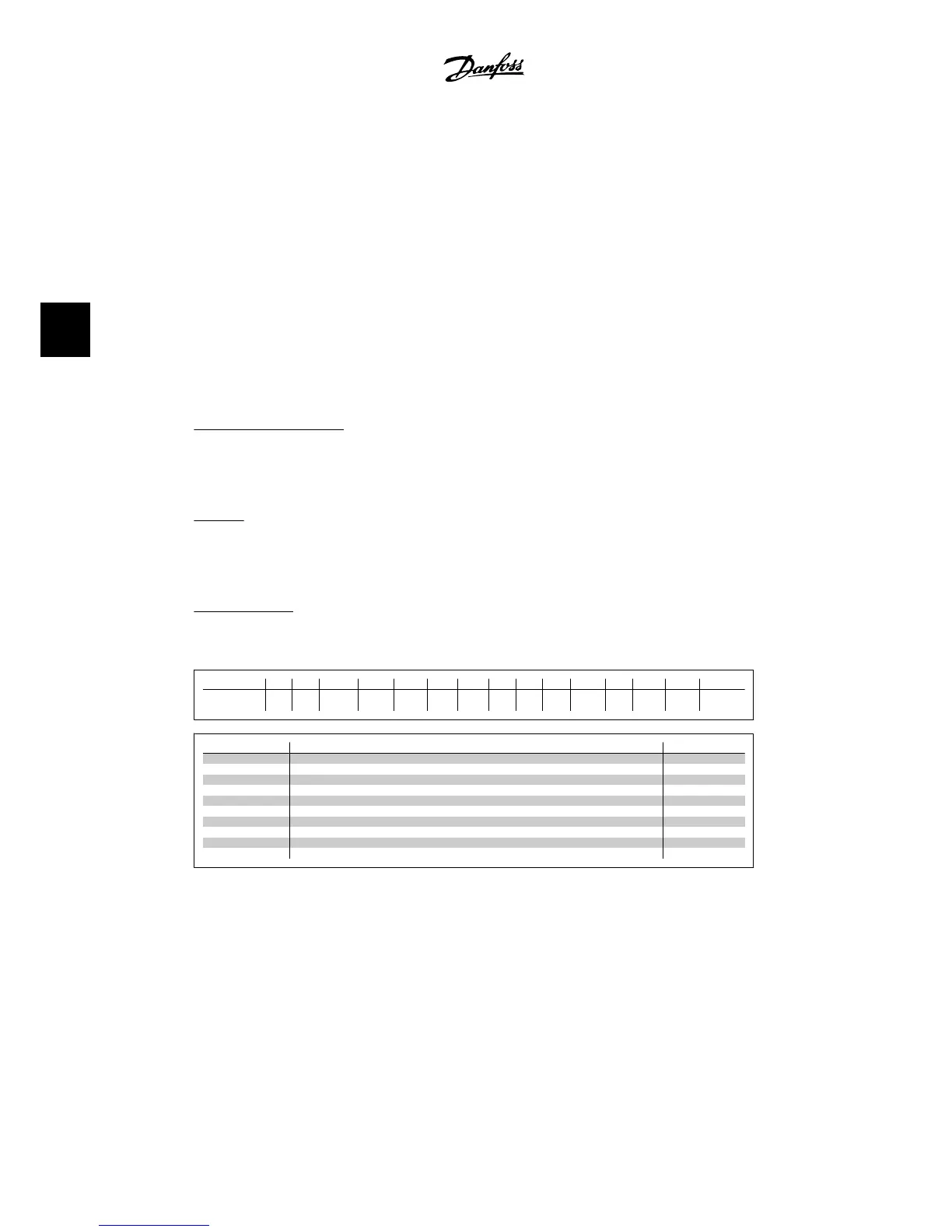
Conversion index
This number refers to a conversion figure used when writing or reading by means of an adjustable
frequency drive.
Conv. index 100 67 6 5 4 3 2 1 0 -1 -2 -3 -4 -5 -6
Conv. factor 1 1/60 100000
0
100000 10000 1000 100 10 1 0.1 0.01 0.00
1
0.000
1
0.0000
1
0.000001
Data type Description Type
2 Integer 8 Int8
3 Integer 16 Int16
4 Integer 32 Int32
5 Unsigned 8 Uint8
6 Unsigned 16 Uint16
7 Unsigned 32 Uint32
9 Visible String VisStr
33 Normalized value 2 bytes N2
35 Bit sequence of 16 Boolean variables V2
54 Time difference w/o date TimD
4. How to Program
VLT
®
HVAC DRIVE High Power
Instruction Manual
84
MG.11.F1.22 - VLT
®
is a registered Danfoss trademark.
4