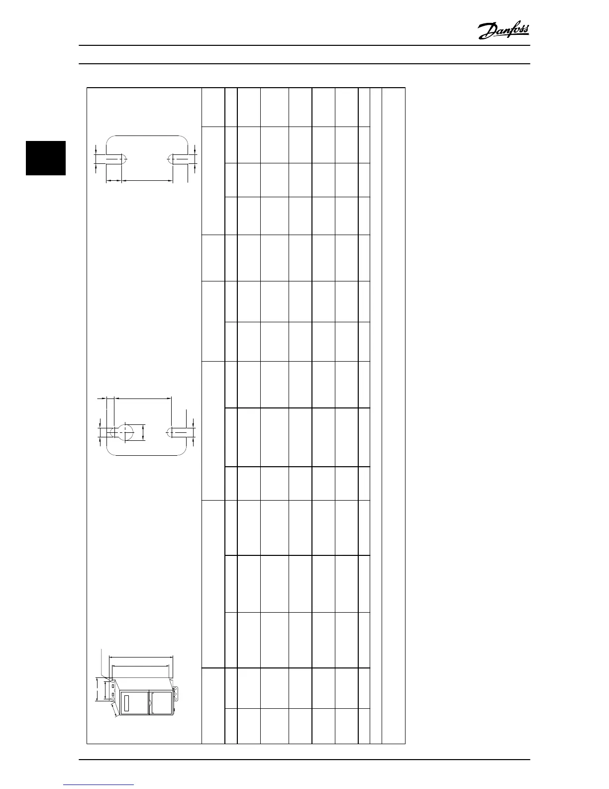
Enclosure Power [kW(HP)] Height [mm (in)] Width [mm(in)] Depth
[mm(in)]
Mounting hole [mm(in] Max.
Weight
Size IP Class 3x200-240 V 3x380-480 V 3x525-600 V A
A
1)
a B b C d e f kg(lb)
I2 IP54 – 0.75–4.0 (1–5) – 332
(13.1)
– 318.5 (12.53) 115 (4.5) 74 (2.9) 225 (8.9) 11 (0.43) 5.5 (0.22) 9 (0.35) 5.3 (11.7)
I3 IP54 – 5.5–7.5 (7.5-10) – 368
(14.5)
– 354 (13.9) 135 (5.3) 89 (3.5) 237 (9.3) 12 (0.47) 6.5 (0.26) 9.5 (0.37) 7.2 (15.9)
I4 IP54 – 11–18.5 (15–25) – 476
(18.7)
– 460 (18.1) 180 (7) 133 (5.2) 290 (11.4) 12 (0.47) 6.5 (0.26) 9.5 (0.37) 13.8
(30.42)
I6 IP54 – 22-37 (30-50) – 650
(25.6)
– 624 (24.6) 242 (9.5) 210 (8.3) 260 (10.2) 19 (0.75) 9 (0.35) 9 (0.35) 27 (59.5)
I7 IP54 – 45-55 (60-70) – 680
(26.8)
– 648 (25.5) 308 (12.1) 272 (10.7) 310 (12.2) 19 (0.75) 9 (0.35) 9.8 (0.39) 45 (99.2)
I8 IP54 – 75-90 (100-125) – 770 (30) – 739 (29.1) 370 (14.6) 334 (13.2) 335 (13.2) 19 (0.75) 9 (0.35) 9.8 (0.39) 65 (143.3)
1) Including decoupling plate
The dimensions are only for the physical units. When installing in an application it is necessary to allow space above and below the units for cooling. The amount of space for free air passage is listed
in Table 3.1.
Table 3.4 Dimensions, Enclosure Size I2-I8
Installation Quick Guide
8 Danfoss A/S © 08/2014 All rights reserved. MG18A602
33