4 Programming
4.1 Local Control Panel (LCP)
NOTICE
The frequency converter can also be programmed from a
PC via the RS-485 COM port by installing the MCT 10
Set-up Software. Refer to chapter 1.2.1 MCT 10 Set-up
Software Support for more details about the software.
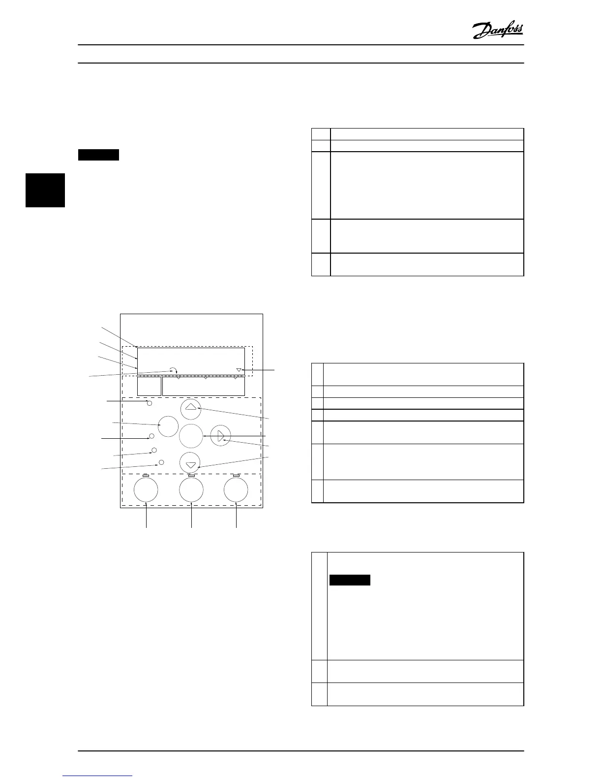
The LCP is divided into 4 functional sections.
A. Display
B. Menu key
C. Navigation keys and indicator lights (LEDs)
D. Operation keys and indicator lights (LEDs)
Illustration 4.1 Local Control Panel (LCP)
A. Display
The LCD-display is back-lit with 2 alphanumeric lines. All
data is displayed on the LCP.
Illustration 4.1 describes the information that can be read
from the display.
1
Parameter number and name.
2 Parameter value.
3 Set-up number shows the active set-up and the edit set-
up. If the same set-up acts as both active and edit set-up,
only that set-up number is shown (factory setting). When
active and edit set-up differ, both numbers are shown in
the display (set-up 12). The number flashing, indicates the
edit set-up.
4 Motor direction is shown to the bottom left of the display
– indicated by a small arrow pointing either clockwise or
counterclockwise.
5 The triangle indicates if the LCP is in status, quick menu or
main menu.
Table 4.1 Legend to Illustration 4.1
B. Menu key
Press [Menu] to select between status, quick menu or main
menu.
C. Navigation keys and indicator lights (LEDs)
6 Com LED: Flashes when bus communication is communi-
cating.
7 Green LED/On: Control section is working correctly.
8 Yellow LED/Warn.: Indicates a warning.
9 Flashing Red LED/Alarm: Indicates an alarm.
10 [Back]: For moving to the previous step or layer in the
navigation structure.
11
[
▲
] [
▼
] [►]: For navigating among parameter groups,
parameters and within parameters. They can also be used for
setting local reference.
12 [OK]: For selecting a parameter and for accepting changes to
parameter settings.
Table 4.2 Legend to Illustration 4.1
D. Operation keys and indicator lights (LEDs)
13
[Hand On]: Starts the motor and enables control of the
frequency converter via the LCP.
NOTICE
[2] coast inverse is the default option for
5-12 Terminal 27 Digital Input. This means that
[Hand On] does not start the motor if there is no
24 V supply to terminal 27. Connect terminal 12 to
terminal 27.
14 [Off/Reset]: Stops the motor (Off). If in alarm mode, the
alarm is reset.
15 [Auto On]: Frequency converter is controlled either via
control terminals or serial communication.
Table 4.3 Legend to Illustration 4.1
Programming
Quick Guide
24 Danfoss A/S © 08/2014 All rights reserved. MG18A602
44