4.8.4 Voltage/Current Input Selection
(Switches)
The analog input terminals 53 and 54 allow setting of
input signal to voltage (0–10 V) or current (0/4–20 mA).
Default parameter settings:
•
Terminal 53: speed reference signal in open-loop
(see 16-61 Terminal 53 Switch Setting).
•
Terminal 54: feedback signal in closed-loop (see
16-63 Terminal 54 Switch Setting).
NOTICE!
Disconnect power to the adjustable frequency drive
before changing switch positions.
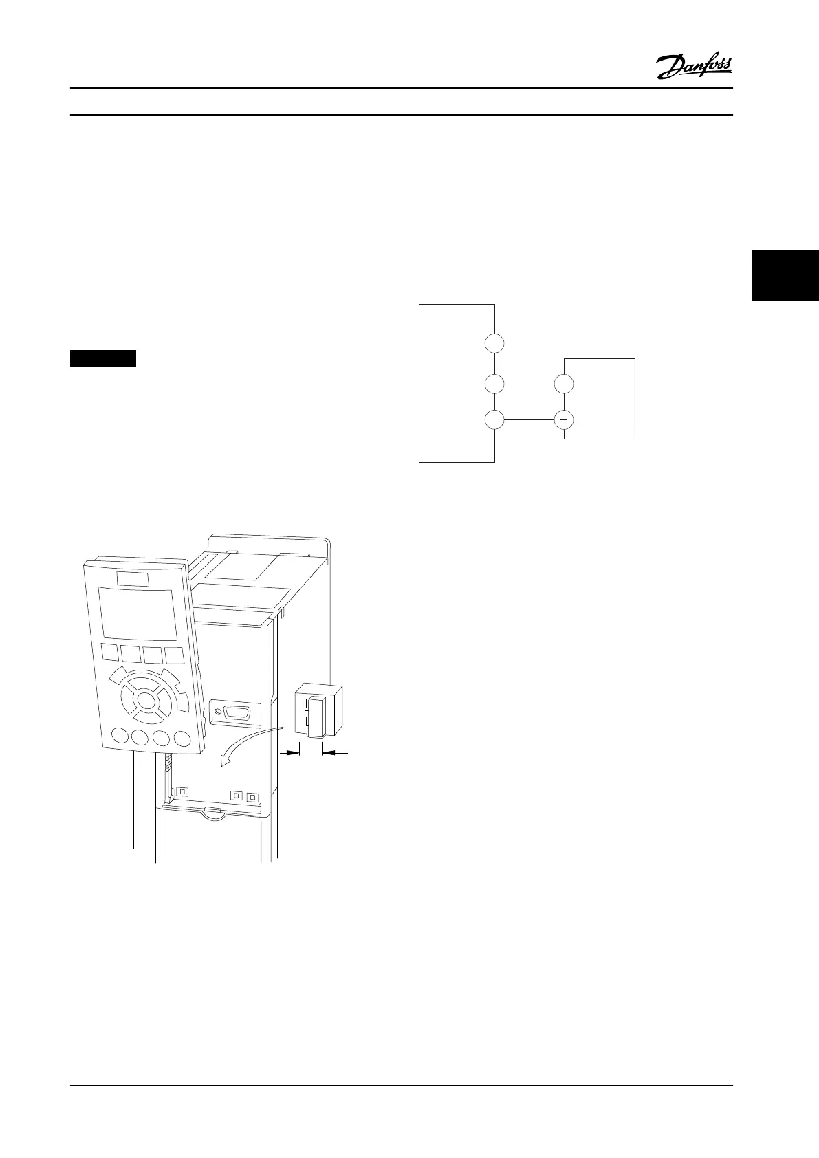
1.
Remove the local control panel (see Figure 4.10).
2. Remove any optional equipment covering the
switches.
3. Set switches A53 and A54 to select the signal
type. U selects voltage, I selects current.
130BD530.10
1
2
N O
VLT
BUSTER.
OFF-ON
A53 A54
U- I U- I
Figure 4.10 Location of Terminals 53 and 54 Switches
4.8.5
Safe Torque Off (STO)
To run Safe Torque Off, additional wiring for the adjustable
frequency drive is required, refer to Safe Torque Off
Instruction Manual for Danfoss VLT
®
Adjustable Frequency
Drives for further information.
4.8.6
RS-485 Serial Communication
Connect RS-485 serial communication wiring to terminals
(+)68 and (-)69.
•
Use shielded serial communication cable
(recommended)
•
See chapter 4.3 Grounding for proper grounding.
61
68
69
+
130BB489.10
RS-485
Figure 4.11 Serial Communication Wiring Diagram
For basic serial communication set-up, select the following:
1.
Protocol type in 8-30 Protocol.
2. Adjustable frequency drive address in
8-31 Address.
3.
Baud rate in 8-32 Baud Rate.
•
Communication protocols are internal to the
adjustable frequency drive.
[0] FC Profile
[1] FC/MC Profile
[2] Modbus RTU
[3] Metasys N2
[9] FC Option
•
Functions can be programmed remotely using
the protocol software and RS-485 connection or
in parameter group 8-** Communications and
Options.
•
Selecting a specific communication protocol
changes various default parameter settings to
match that protocol’s specifications along with
making additional protocol-specific parameters
available.
•
Option cards which can be installed in the
adjustable frequency drive are available to
provide additional communication protocols. See
the option-card documentation for installation
and operation instructions.
Electrical Installation
Instruction Manual
MG16E322 Danfoss A/S © Rev. 2014-04-10 All rights reserved. 21
4 4