7 Maintenance, Diagnostics and Troubleshooting
This chapter includes maintenance and service guidelines,
status messages, warnings and alarms and basic trouble-
shooting.
7.1 Maintenance and Service
Under normal operating conditions and load profiles, the
adjustable frequency drive is maintenance-free throughout
its designed lifetime. To prevent breakdown, danger, and
damage, examine the adjustable frequency drive at regular
intervals depending on the operating conditions. Replace
worn or damaged parts with original spare parts or
standard parts. For service and support, refer to
www.danfoss.com/contact/sales_and_services/.
WARNING
HIGH VOLTAGE
Adjustable frequency drives contain high voltage when
connected to AC line power. Failure to perform instal-
lation, start-up, and maintenance by qualified personnel
could result in death or serious injury.
•
Installation, start-up, and maintenance must be
performed by qualified personnel only.
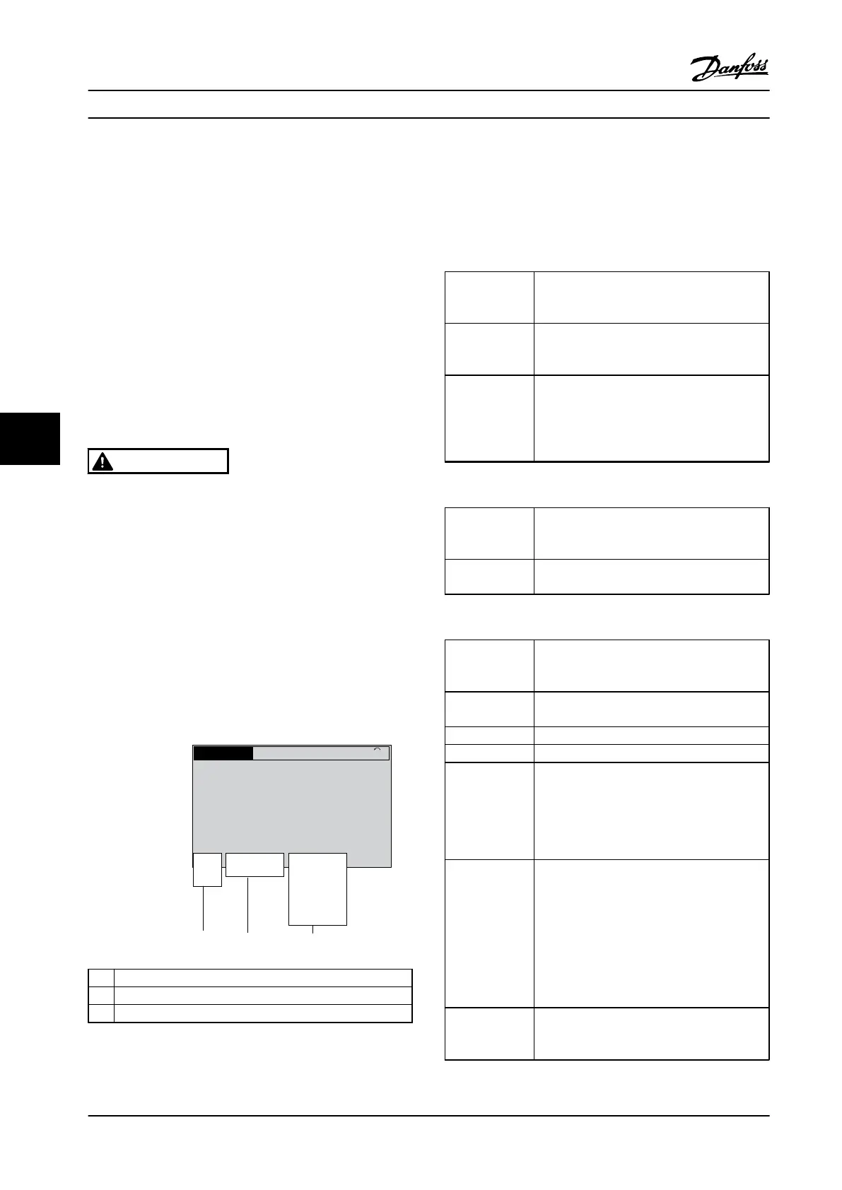
7.2 Status Messages
When the adjustable frequency drive is in status mode,
status messages are generated automatically and appear in
the bottom line of the display (see Figure 7.1).
Status
799RPM 7.83A 36.4kW
0.000
53.2%
1(1)
Auto
Hand
O
Remote
Local
Ramping
Stop
Running
Jogging
.
.
.
Stand by
130BB037.11
1 2 3
1
Operation mode (see Table 7.1)
2
Reference site (see Table 7.2)
3
Operation status (see Table 7.3)
Figure 7.1 Status Display
Table 7.1 to Table 7.3 describe the displayed status
messages.
Off The adjustable frequency drive does not react
to any control signal until [Auto On] or [Hand
On] is pressed.
Auto On The adjustable frequency drive is controlled
from the control terminals and/or the serial
communication.
The adjustable frequency drive is controlled
by the navigation keys on the LCP. Stop
commands, reset, reversing, DC brake, and
other signals applied to the control terminals
override local control.
Table 7.1 Operation Mode
Remote The speed reference is given from external
signals, serial communication, or internal
preset references.
Local The adjustable frequency drive uses [Hand On]
control or reference values from the LCP.
Table 7.2 Reference Site
AC Brake
AC Brake was selected in 2-10 Brake Function.
The AC brake overmagnetizes the motor to
achieve a controlled slow-down.
AMA finish OK Automatic motor adaptation (AMA) was
carried out successfully.
AMA ready AMA is ready to start. Press [Hand On] to start.
AMA running AMA process is in progress.
Coast
•
Coast inverse was selected as a function
for a digital input (parameter group 5-1*
Digital Inputs). The corresponding terminal
is not connected.
•
Coast activated by serial communication
Ctrl. Ramp-down Control Ramp-down was selected in
14-10 Mains Failure.
•
The AC line voltage is below the value set
in 14-11 Mains Voltage at Mains Fault at
line power fault
•
The adjustable frequency drive ramps
down the motor using a controlled ramp-
down.
Current High The adjustable frequency drive output current
is above the limit set in 4-51 Warning Current
High.
Maintenance, Diagnostics an... Instruction Manual
36 Danfoss A/S © Rev. 2014-04-10 All rights reserved. MG16E322
77