Control card, 10 V DC output
Terminal number 50
Output voltage 10.5 V ±0.5 V
Max. load 15 mA
The 10 V DC supply is galvanically isolated from the supply voltage (PELV) and other high-voltage terminals.
Control characteristics
Resolution of output frequency at 0–590 Hz ± 0.003 Hz
Repeat accuracy of Precise start/stop (terminals 18, 19) ≤± 0.1 ms
System response time (terminals 18, 19, 27, 29, 32, 33) ≤ 2 ms
Speed control range (open-loop) 1:100 of synchronous speed
Speed control range (closed-loop) 1:1000 of synchronous speed
Speed accuracy (open-loop) 30–4000 rpm: error ±8 rpm
Speed accuracy (closed-loop), depending on resolution of feedback device 0–6000 rpm: error ±0.15 rpm
All control characteristics are based on a 4-pole asynchronous motor
Control card performance
Scan interval 1 ms
Control card, USB serial communication
USB standard 1.1 (full speed)
USB plug USB type B “device” plug
Connection to PC is carried out via a standard host/device USB cable.
The USB connection is galvanically isolated from the supply voltage (PELV) and other high-voltage terminals.
The USB ground connection is not galvanically isolated from protection ground. Use only an isolated laptop as PC connection to
the USB connector on the adjustable frequency drive.
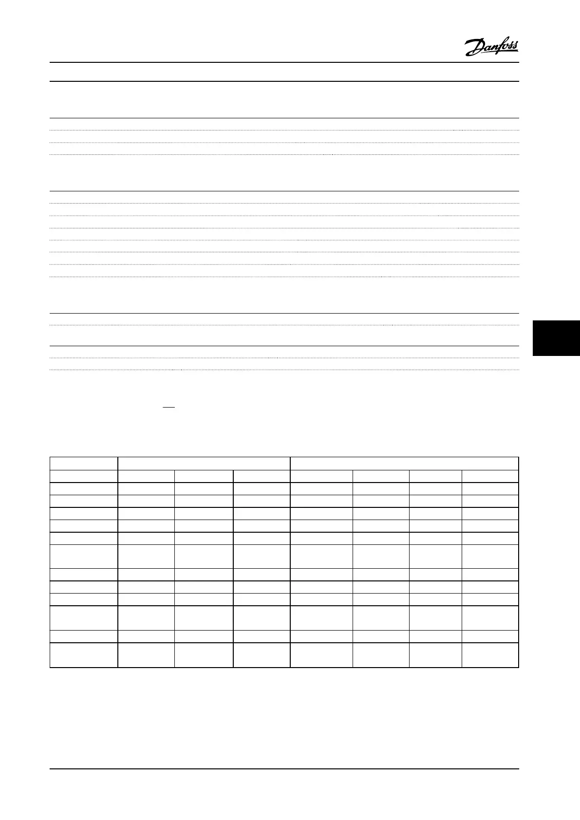
8.7
Connection Tightening Torques
Power (hp [kW]) Torque (in-lb [Nm])
Enclosure 200–240 V 380–480 V 525–600 V Line power Motor Ground Relay
A2 1.5–3 [1.1–2.2] 1.5–5 [1.1–4.0] 15.93 [1.8] 15.93 [1.8] 26.55 [3] 5.31 [0.6]
A3 4–5 [3.0–3.7] 7.5–10 [5.5–7.5] 1.5–10 [1.1–7.5] 15.93 [1.8] 15.93 [1.8] 26.55 [3] 5.31 [0.6]
A4 1.5–3 [1.1–2.2] 1.5–5 [1.1–4.0] 15.93 [1.8] 15.93 [1.8] 26.55 [3] 5.31 [0.6]
A5 1.5–5 [1.1-3.7] 1.5–10 [1.1–7.5] 1.5–10 [1.1–7.5] 15.93 [1.8] 15.93 [1.8] 26.55 [3] 5.31 [0.6]
B1 7.5–10 [5.5–7.5] 15–20 [11–15] 15–20 [11–15] 15.93 [1.8] 15.93 [1.8] 26.55 [3] 5.31 [0.6]
B2 15 [11]
24 [18]
30 [22]
24 [18]
30 [22]
39.83 [4.5]
39.83 [4.5]
39.83 [4.5]
39.83 [4.5]
26.55 [3]
26.55 [3]
5.31 [0.6]
5.31 [0.6]
B3 7.5–10 [5.5–7.5] 15–20 [11–15] 15–20 [11–15] 15.93 [1.8] 15.93 [1.8] 26.55 [3] 5.31 [0.6]
B4 15–20 [11–15] 24–40 [18–30] 24–40 [18–30] 39.83 [4.5] 39.83 [4.5] 26.55 [3] 5.31 [0.6]
C1 20–30 [15–22] 40–60 [30–45] 40–60 [30–45] 88.51 [10] 88.51 [10] 26.55 [3] 5.31 [0.6]
C2 40–50 [30–37] 75–100 [55–75] 75–100 [55–75]
123.91/212.42
[14/24]
1)
123.91/212.42
[14/24]
1)
26.55 [3] 5.31 [0.6]
C3 24–30 [18–22] 50–60 [37–45] 50–60 [37–45] 88.51 [10] 88.51 [10] 26.55 [3] 5.31 [0.6]
C4 40–50 [30–37] 75–100 [55–75] 75–100 [55–75]
123.91/212.42
[14/24]
1)
123.91/212.42
[14/24]
1)
26.55 [3] 5.31 [0.6]
Table 8.7 Tightening of Terminals
1)
For different cable dimensions x/y, where x
≤
4/0 AWG [95 mm
2
] and y
≥
4/0 AWG [95 mm
2
].
Specifications Instruction Manual
MG16E322 Danfoss A/S © Rev. 2014-04-10 All rights reserved. 59
8 8