NOTE!
Max. output frequency cannot exceed 10% of the inverter
switching frequency (14-01 Switching Frequency).
4-16 Torque Limit Motor Mode
Range: Function:
Application
dependent
*
[Application
dependant]
This function limits the
torque on the shaft to
protect the mechanical
installation.
NOTE!
Changing 4-16 Torque Limit Motor Mode when 1-00 Configu-
ration Mode is set to Speed open-loop [0], 1-66 Min. Current at
Low Speed is automatically readjusted.
NOTE!
The torque limit reacts on the actual, non-filtrated torque,
including torque spikes. This is not the torque that is seen
from the LCP or the serial communication bus as that is
filtered.
4-17 Torque Limit Generator Mode
Range: Function:
100.0 %
*
[Application
dependant]
This function limits the torque on
the shaft to protect the
mechanical installation.
NOTE!
The torque limit reacts on the actual, non-filtrated torque,
including torque spikes. This is not the torque that is seen
from the LCP or the serial communication bus as that is
filtered.
4-18 Current Limit
Range: Function:
Application
dependent
*
[Application
dependant]
This is a true current limit function
that continues in the oversyn-
chronous range; however, due to
field weakening, the motor torque
at current limit will drop
accordingly when the voltage
increase stops above the
synchronized speed of the motor.
4-19 Max Output Frequency
Range: Function:
132.0 Hz
*
[1.0 -
1000.0 Hz]
Provides a final limit on the output
frequency for improved safety in
applications where you want to avoid
accidental overspeeding. This limit is final
in all configurations (independent of the
setting in 1-00 Configuration Mode).
NOTE!
Max. output frequency cannot exceed 10% of the inverter
switching frequency (14-01 Switching Frequency).
4-19 Max Output Frequency cannot be adjusted while the
motor is running.
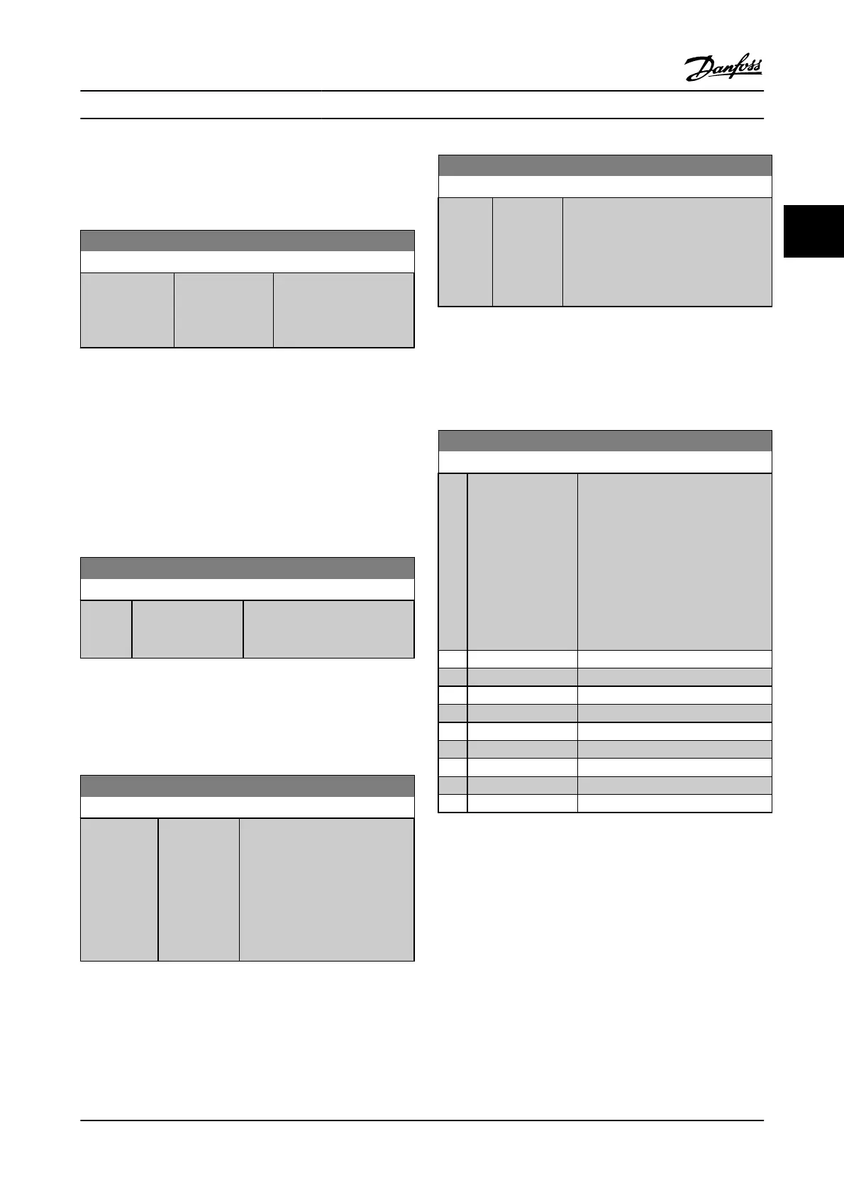
4-20 Torque Limit Factor Source
Option: Function:
Select an analog input for scaling the
settings in 4-16 Torque Limit Motor
Mode and 4-17 Torque Limit Generator
Mode from 0% to 100% (or inverse).
The signal levels corresponding to 0%
and 100% are defined in the analog
input scaling, e.g., par. group 6-1*. This
parameter is only active when
1-00 Configuration Mode is in Speed
Open-loop or Speed Closed-loop.
[0]
*
No function
[2] Analog in 53
[4] Analog in 53 inv
[6] Analog in 54
[8] Analog in 54 inv
[10] Analog in X30-11
[12] Analog in X30-11 inv
[14] Analog in X30-12
[16] Analog in X30-12 inv
Parameter Descriptions FC 300 Programming Guide
MG.33.MA.22 - VLT
®
is a registered Danfoss trademark 3-43
3

 Loading...


