4-21 Speed Limit Factor Source Option
Option: Function:
Select an analog input for scaling the
settings in par. 4-19 from 0% to 100%
(or vice versa). The signal levels
corresponding to 0% and 100% are
defined in the analog input scaling,
such as par. group 6-1*, for example.
This parameter is only active when
par. 1-00 Configuration Mode is in
Torque Mode.
[0]
*
No function
[2] Analog input 53
[4] Analog input 53 inv
[6] Analog input 54
[8] Analog input 54 inv
[10] Analog input X30-11
[12] Analog input X30-11
inv
[14] Analog input X30-12
[16] Analog input X30-12
inv
3.6.2 4-3* Motor Feedback Monitoring
The par. group includes monitoring and handling of motor
feedback devices as encoders, resolvers, etc.
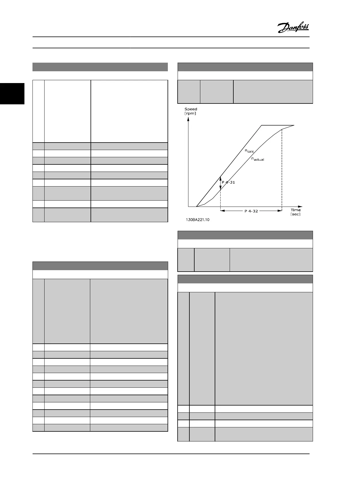
4-30 Motor Feedback Loss Function
Option: Function:
Select which reaction the adjustable
frequency drive should take if a
feedback fault is detected. The
selected action is to take place when
the feedback signal differs from the
output speed where its range is
specified in 4-31 Motor Feedback
Speed Error during its time frame set
in 4-32 Motor Feedback Loss Timeout.
[0] Disabled
[1] Warning
[2]
*
Trip
[3] Jog
[4] Freeze Output
[5] Max Speed
[6] Switch to Open Loop
[7] Select Set-up 1
[8] Select Set-up 2
[9] Select Set-up 3
[10] Select Set-up 4
[11] stop & trip
4-31 Motor Feedback Speed Error
Range: Function:
300 RPM
*
[1 - 600 RPM] Select the max. allowed tracking error
in speed from the calculated and the
actual mechanical shaft output speeds.
4-32 Motor Feedback Loss Timeout
Range: Function:
0.05 s
*
[0.00 - 60.00 s] Set the timeout value allowing the speed
error set in 4-31 Motor Feedback Speed
Error to be exceeded.
4-34 Tracking Error Function
Option: Function:
Select which reaction the adjustable frequency
drive should take if a tracking error is detected.
Closed-loop: The tracking error is measured
between the output from the ramp generator
and the speed feedback (filtered).
Open-loop: The tracking error is measured
between the output from the ramp generator -
compensated for slip - and the frequency that is
sent to the motor (16-13).
The reaction will be activated if the measured
difference is more than specified in par. 4-35 for
the time specified in par. 4-36.
A tracking error in closed-loop does not imply
that there is a problem with the feedback signal!
A tracking error can be the result of torque limit
for loads that are too big.
[0]
*
Disable
[1] Warning
[2] Trip
[3] Trip after
stop
Parameter Descriptions FC 300 Programming Guide
3-44 MG.33.MA.22 - VLT
®
is a registered Danfoss trademark
3

 Loading...


