3.5.1. Electrical Installation, Control Cables
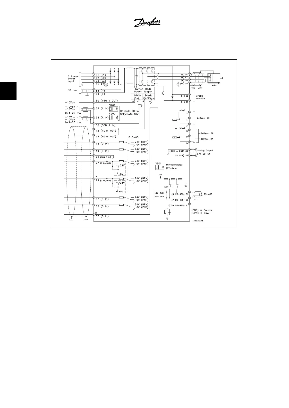
3.12: Diagram showing all electrical terminals without options.
Terminal 37 is the input to be used for Safe Stop. For instructions on safe stop installation, refer to the section
Safe Stop Installation in the FC 300 Design Guide.
* Terminal 37 is not included in the FC 301 (Except the FC 301 A1, which includes Safe Stop).
Terminal 29 and Relay 2 are not included in FC 301.
In rare cases, very long control cables and analog signals may, depending on installation, result
in 50/60 Hz ground loops due to noise from line supply cables.
If this occurs, it may be necessary to break the shield or insert a 100 nF capacitor between shield
and chassis.
The digital and analog inputs and outputs must be connected separately to the FC 300 common
inputs (terminal 20, 55, 39) to avoid letting ground currents from both groups affect other groups.
For example, switching on the digital input may disturb the analog input signal.
3. How to Install
VLT
®
AutomationDrive FC 300 Instruction
Manual
38
MG.33.A9.22 - VLT is a registered Danfoss trademark
3