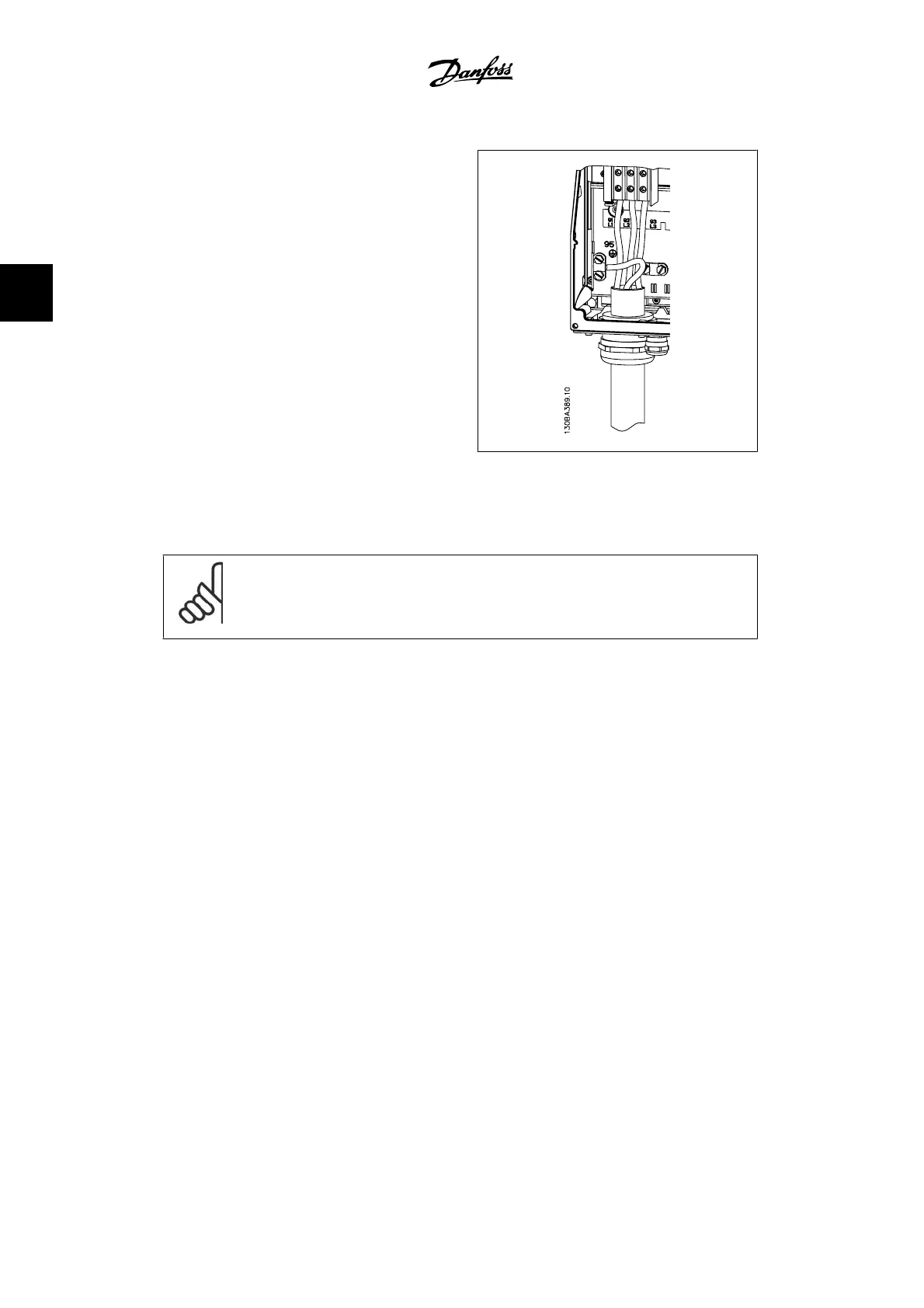
Line connection C1 and C2 (IP 21/ NEMA Type
1 and IP 55/66/ NEMA Type 12) enclosures
The power cables for line power are usually non-shielded cables.
3.3.3. Motor Connection
NOTE
Motor cable must be shielded/armored. The use of an unshielded/unarmored cable
is against EMC requirements. Use a shielded/armored motor cable to comply with
EMC emission specifications. For more information, see
EMC Test Results
.
See section General Specifications for correct dimensioning of motor cable cross-section and
length.
Shielding of cables: Avoid installation with twisted shield ends (pigtails). They spoil the shielding
effect at higher frequencies. If it is necessary to break the shield to install a motor isolator or
motor contactor, the shield must be continued at the lowest possible HF impedance.
Connect the motor cable shield to both the FC 300 decoupling plate and the motor's metal housing.
Make the shield connections with the largest possible surface area (cable clamp). This is done by
using the supplied installation devices in the FC 300.
If it is necessary to split the shield to install a motor isolator or motor relay, the shield must be
continued with the lowest possible HF impedance.
Cable length and cross-section: The adjustable frequency drive has been tested with a given
length of cable and a given cross-section of that cable. If the cross-section is increased, the cable
capacitance - and thus the leakage current - may increase, thereby requiring that the cable length
is reduced accordingly. Keep the motor cable as short as possible to reduce the noise level and
leakage currents.
Switching frequency: When adjustable frequency drives are used together with sine-wave fil-
ters to reduce the acoustic noise from a motor, the switching frequency must be set according to
the sine-wave filter instructions in par. 14-01.
1. Fasten decoupling plate to the bottom of the FC 300 with screws and washers from the
accessory bag.
3. How to Install
VLT
®
AutomationDrive FC 300 Instruction
Manual
24
MG.33.A9.22 - VLT is a registered Danfoss trademark
3