EasyManuals Logo

Danfoss FC 301 User Manual

Danfoss FC 301
98 pages
To Next Page IconTo Next Page
To Previous Page IconTo Previous Page
Page #37 background imageLoading...
Page #37 background image
3.4.3. Speed Up/Slow
Terminals 29/32 = Speed up/Slow: .
Terminal 18 = Par. 5-10 [9]
Start
(default)
Terminal 27 = Par. 5-12 [19]
Freeze
reference
Terminal 29 = Par. 5-13 [21]
Speed
up
Terminal 32 = Par. 5-14 [22]
Slow
Note: Terminal 29 only in FC x02 (x=series
type).
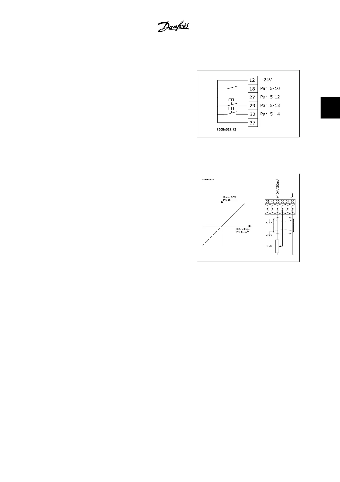
3.4.4. Potentiometer Reference
Voltage reference via a potentiometer:
Reference Source 1 = [1]
Analog in-
put 53
(default)
Terminal 53, Low Voltage = 0 Volt
Terminal 53, High Voltage = 10 Volt
Terminal 53, Low Ref./Feedback = 0
RPM
Terminal 53, High Ref./Feedback =
1500 RPM
Switch S201 = OFF (U)
VLT
®
AutomationDrive FC 300 Instruction
Manual
3. How to Install
MG.33.A9.22 - VLT is a registered Danfoss trademark
37
3

Other manuals for Danfoss FC 301

Questions and Answers:

Question and Answer IconNeed help?

Do you have a question about the Danfoss FC 301 and is the answer not in the manual?

Danfoss FC 301 Specifications

General IconGeneral
TypeAC Drive
Output frequency0-1000 Hz
Enclosure ratingIP20, IP21, IP55
Control methodSensorless vector control
Communication optionsRS-485, CANopen, Profibus DP
Ambient temperature-10°C to +50°C
Supply voltage200-240 V, 380-500 V, 525-690 V
Protection classIP20, IP21, IP55
Cooling methodForced air
Relative humidity5% to 95% (non-condensing)
Storage temperature range-25 to 70 °C (-13 to 158 °F)

Related product manuals