2.6 AC Grid Connection
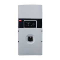
Illustration 2.15 Installation Area
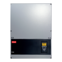
Illustration 2.16 AC Cable Wire Strip
On the AC cable, strip insulation on all 5 wires. The PE wire
must be longer than the mains and neutral wires. See
Illustration 2.16.
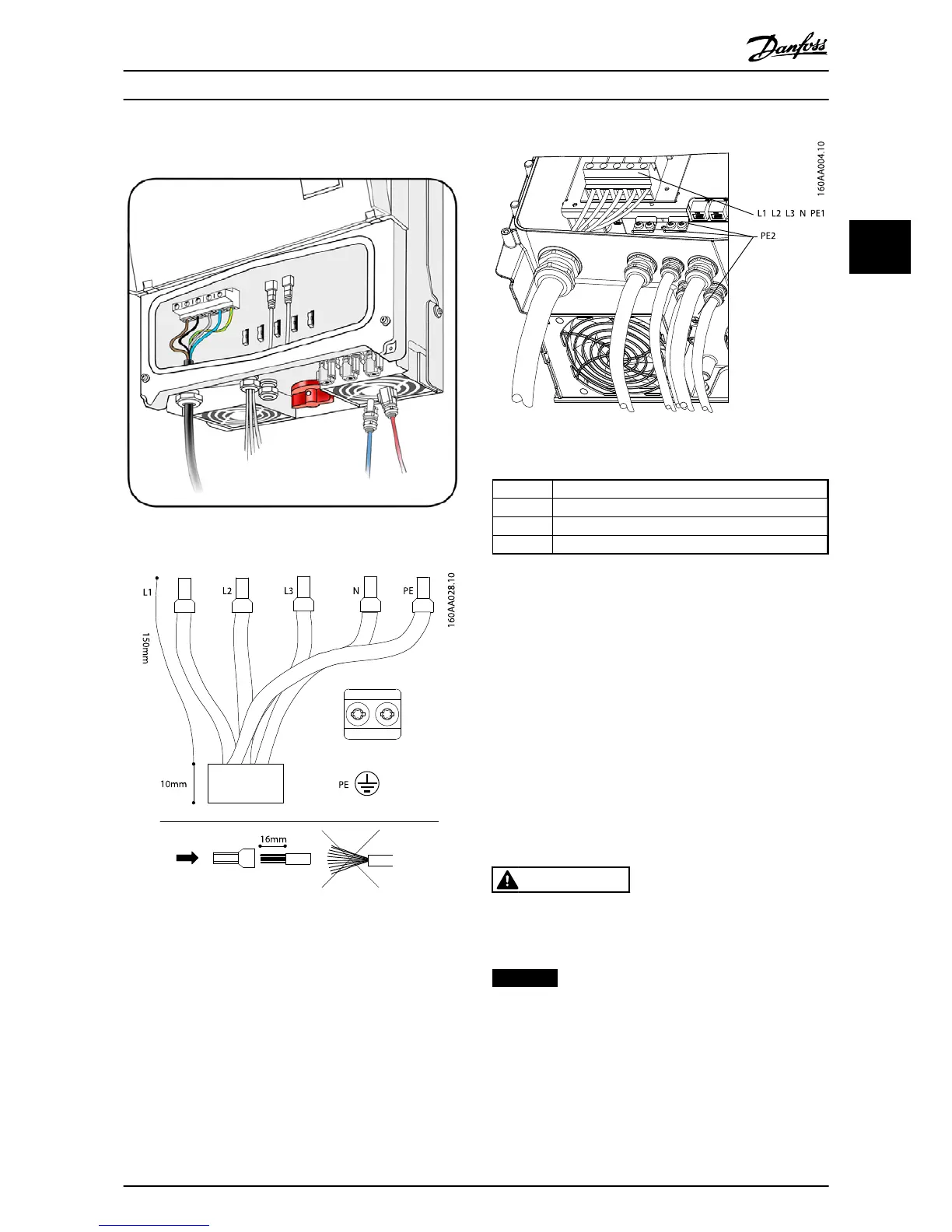
Illustration 2.17 AC Connection Area
L1, L2, L3 3 mains wires
NNeutral wire
PE1 Primary protective earth
PE2 Secondary protective earth
1. Verify that the inverter rating matches the grid.
2. Ensure that main circuit breaker is released, and
take precautions to prevent reconnection.
3. Open the front cover.
4. Insert the cable through the AC gland to the
terminal blocks.
5. Connect the 3 mains wires (L1, L2, L3), the
neutral wire (N) and the protective earth wire (PE)
to the terminal block with the respective
markings.
6. Optional: Make an extra PE connection at the
secondary PE earthing points.
7. All wires must be properly fastened with the
correct torque. See 5.6 Torque Specifications.
CAUTION
Check that all wiring is correct. Connecting a phase wire
to the neutral terminal may permanently damage the
inverter.
NOTICE
Tighten all screws and glands thoroughly.
Installation
L00410568-02_02 / Rev. date: 2013-12-10 11
2