Illustration 5.15 RJ-45 Pinout Detail for Ethernet
Pinout
Ethernet
Colour Standard
Cat 5
T-568A
Cat 5
T-568B
1. RX+ Green/white Orange/white
2. RX Green Orange
3. TX+ Orange/white Green/white
4. Blue Blue
5. Blue/white Blue/white
6. TX- Orange Green
7. Brown/white Brown/white
8. Brown Brown
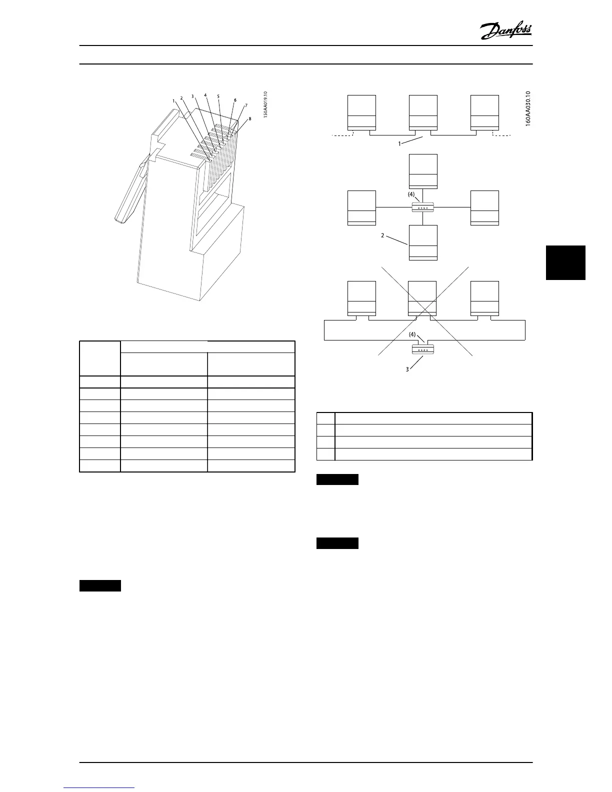
5.9.1 Network Topology
The inverter has 2 Ethernet RJ-45 connectors enabling the
connection of several inverters in a line topology as an
alternative to the typical star topology. The 2 ports are
similar and may be used interchangeably. For RS-485, only
linear daisy chain connections can be used.
NOTICE
Ring topology is not permitted.
Illustration 5.16 Network Topology
1Linear Daisy Chain
2Star Topology
3 Ring Topology (not permitted)
(4) (Ethernet Switch)
NOTICE
The 2 network types cannot be mixed. The inverters can
only be connected in networks which are either solely
RS-485 or solely Ethernet.
NOTICE
Ethernet is recommended for faster communication.
RS-485 is required when a weblogger or datalogger is
connected to the inverter.
Technical Data
L00410568-02_02 / Rev. date: 2013-12-10 45
5