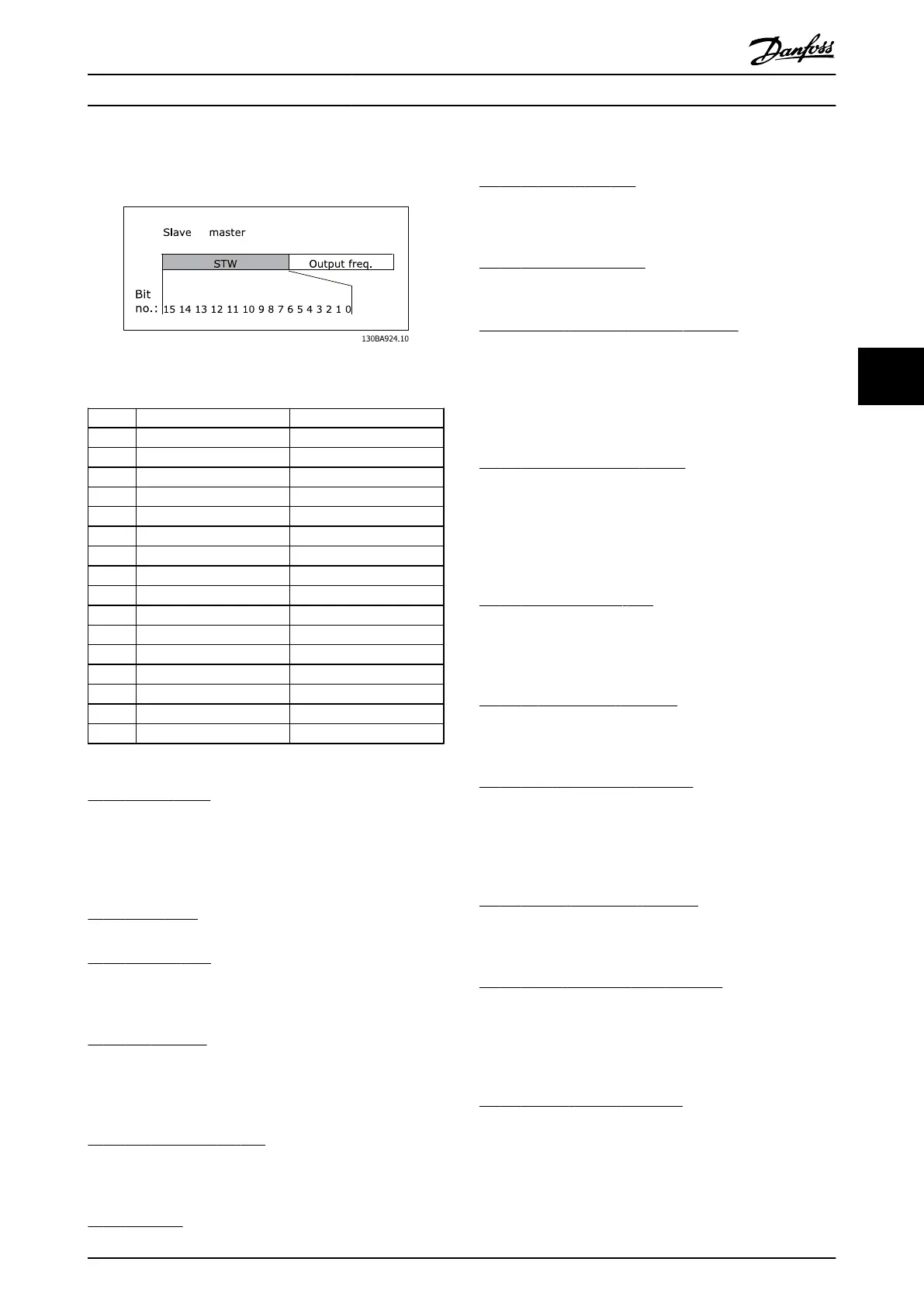
5.2.2 Status Word according to FC Profile
(STW)
Illustration 5.2 (8-10 Control Word Profile)
Bit Bit value = 0 Bit value = 1
00 Control not ready Control ready
01 Drive not ready Drive ready
02 Coasting Enable
03 No error Trip
04 No error Error (no trip)
05 Reserved -
06 No error Trip lock
07 No warning Warning
08 Speed ≠ reference Speed = reference
09 Local operation Bus control
10 Out of frequency limit Frequency limit ok
11 No operation In operation
12 Drive ok Stopped, auto start
13 Voltage ok Voltage exceeded
14 Torque ok Torque exceeded
15 Thermal ok Thermal exceeded
Explanation of the Status Bits
Bit 00, Control ready:
Bit 00 = ‘0’ means that the frequency converter has
tripped. Bit 00 = ‘1’ means that the frequency converter
controls are ready, but that the power component is not
necessarily receiving any power supply (in the event of
external 24V supply to controls).
Bit 01, Drive ready:
Bit 01 = ‘1’. The frequency converter is ready for operation.
Bit 02, Coasting stop:
Bit 02 = ‘0’. The frequency converter has released the
motor. Bit 02 = ‘1’. The frequency converter can start the
motor when a start command is given.
Bit 03, No error/Trip:
Bit 03 = ‘0’ means that the frequency converter is not in
fault mode. Bit 03 = ‘1’ means that the frequency
converter is tripped, and that a reset signal is required to
re-establish operation.
Bit 04, No error/Error (no trip):
Bit 04 = ‘0’ means that the frequency converter is not in
fault mode. Bit 04 = ‘1’ means that there is a frequency
converter error but no trip.
Bit 05, Reserved:
Bit 05 is not used in the status word.
Bit 06, No error / Trip lock:
Bit 06 = ‘0’ means that the frequency converter is not in
fault mode. Bit 06 = ‘1’ means that the frequency
converter is tripped, and locked.
Bit 07, No warning/Warning:
Bit 07 = ‘0’ means that there are no warnings. Bit 07 = ‘1’
means that a warning has occurred.
Bit 08, Speed≠ reference/Speed = reference:
Bit 08 = ‘0’ means that the motor is running, but that the
present speed is different from the preset speed reference.
For example, this might occur while the speed is being
ramped up/down during start/stop. Bit 08 = ‘1’ means that
the present motor speed matches the preset speed
reference.
Bit 09, Local operation/Bus control:
Bit 09 = ‘0’ means that [STOP/RESET] is activated on the
control unit, or that Local control in 3-13 Reference Site is
selected. It is not possible to control the frequency
converter via serial communication. Bit 09 = ‘1’ means that
it is possible to control the frequency converter via the
fieldbus/ serial communication.
Bit 10, Out of frequency limit:
Bit 10 = ‘0’, if the output frequency has reached the value
in 4-11 Motor Speed Low Limit [RPM] or 4-13 Motor Speed
High Limit [RPM]. Bit 10 = ‘1’ means that the output
frequency is within the defined limits.
Bit 11, No operation/In operation:
Bit 11 = ‘0’ means that the motor is not running. Bit 11 =
‘1’ means that the frequency converter has a start signal or
that the output frequency is greater than 0 Hz.
Bit 12, Drive OK/Stopped, auto start:
Bit 12 = ‘0’ means that there is no temporary over
temperature on the inverter. Bit 12 = ‘1’ means that the
inverter has stopped because of over temperature, but
that the unit has not tripped and will resume operation
once the over temperature stops.
Bit 13, Voltage OK/Voltage exceeded:
Bit 13 = ‘0’ means that there are no voltage warnings. Bit
13 = ‘1’ means that the DC voltage in the frequency
converter’s intermediate circuit is too low or too high.
Bit 14, Torque OK/Torque limit exceeded:
Bit 14 = ‘0’ means that the motor current is lower than the
torque limit selected in par. 4-16 and 4-17 Torque limit. Bit
14 = ‘1’ means that the torque limit in par. 4-16 and 4-17
Torque limit has been exceeded. The nominal torque can
be read in 16-16 Torque [Nm].
Bit 15, Thermal OK/limit exceeded:
Bit 15 = ‘0’ means that the timers for both motor thermal
protection and frequency converter thermal protection,
have not exceeded 100%. Bit 15 = ‘1’ means that one of
the limits has exceeded 100%.
How to Control MCA 121 EtherNet/IP
MG.90.J3.02 - VLT
®
is a registered Danfoss trademark 23
5 5