- Push the fieldbus option adaptor frame for the
frequency converter into place.
- Replace the LCP and attach cable
NOTE
Do not strip the Ethernet cable and ground it via the strain
relief-plate! The grounding of screened Ethernet cable is
done through the RJ-45 connector on the option.
NOTE
After installing the MCA 121 option, be aware of the
following parameter settings:
8-01 Control Site: [2] Controlword only or [0] Digital and ctrl.
word
8-02 Control Word Source: [3] Option A
14-89 Option Detection: [1] Enable option Change
3.1.3 LED Behaviour
The option has 3 bi-coloured LEDs according to ODVA
specifications:
LED Label Description
MS Module Status
NS1 Network Status Ethernet Port 1
NS2 Network Status Ethernet Port 2
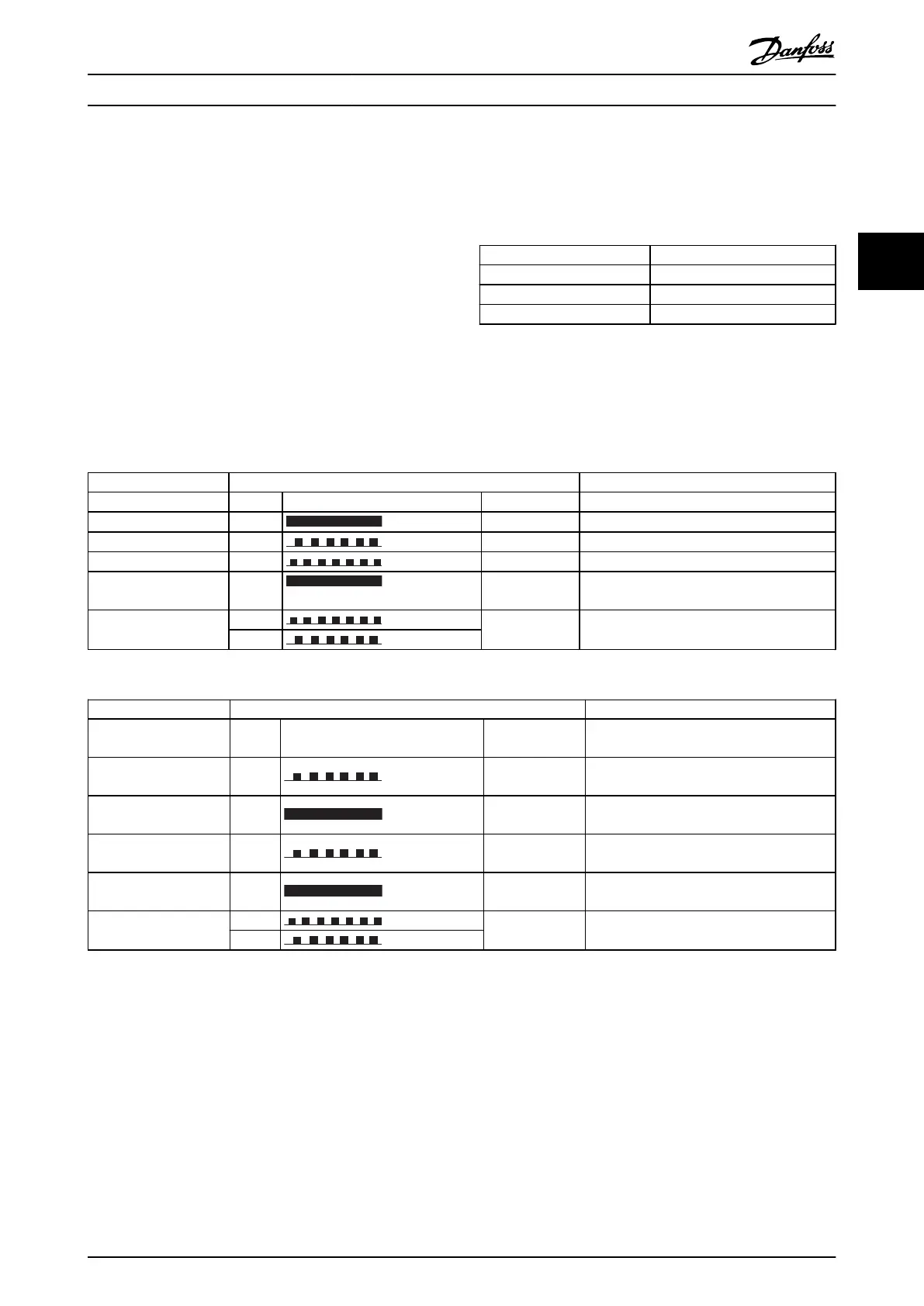
The option LEDs operate according to ODVA specifications.
State LED Description
No power Off The device is un-powered
Device operational Green: Solid green The device is operational
Standby Green: Flashing green The device needs commissioning
Minor fault Red: Flashing red The device has detected a recoverable fault
Major fault Red: Solid red The device has detected an un-recoverable
fault
Self test
Red:
Flashing red/
green
The EIP option is in self-test mode
Green:
Table 3.1 MS: Module Status
State LED Description
No IP-address (no
power)
Off
The device does not have a valid IP-address
(or is un-powered)
No connections Green: Flashing green
There are no established CIP connections to
the device
Connected Green: Solid green
There is established (at least) one CIP
connection to the device
Connection time-out Red: Flashing red
One or more CIP connections have timed-
out
Duplicate IP Red: Solid red
The IP-address assigned to the device is
already in use
Self test
Red:
Flashing red/
green
The EIP option is in self-test mode
Green
Table 3.2 NS1 + NS2: Network Status (one per port)
During normal operation the MS and at least one NS LED will show a constant green light.
How to Install MCA 121 EtherNet/IP
MG.90.J3.02 - VLT
®
is a registered Danfoss trademark 7
3
3