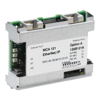
Do you have a question about the Danfoss MCA 121 and is the answer not in the manual?
| Device Type | Media Converter |
|---|---|
| Model | MCA 121 |
| Manufacturer | Danfoss |
| Serial Interface | RS-485 |
| Ethernet Interface | 10/100Base-TX |
| Mounting | DIN rail |
| Protection Class | IP20 |
| Power Supply | 24 V DC |
| Operating Voltage | 24 V DC ±10% |
| Storage Temperature | -40°C to +85°C |
| Humidity | 5 – 95% RH, non-condensing |
| Certifications | CE, UL |
| Dimensions (W x H x D) | 22.5 x 99 x 114 mm |
Important safety note regarding high voltage and personal injury risks.
Essential safety regulations for operating and maintaining the frequency converter.
Warning about potential unintended motor start during operation or maintenance.
Overview of the manual's structure, content, and intended audience.
Technical introduction to EtherNet/IP and its role in automation.
Specifics of the MCA 121 EtherNet/IP option hardware.
List of related Danfoss documentation for the product.
Information on the EtherNet/IP option's conformance to ODVA standards.
Glossary of abbreviations used throughout the manual.
Overview of the EtherNet/IP option hardware and its components.
Step-by-step instructions for installing the option into the converter.
Explanation of the status and network LEDs on the option.
Description of network topologies (star, line) supported by MCA 121.
Requirements and recommendations for the Ethernet network media and components.
Guidelines for designing robust Ethernet networks with the option.
Precautions to ensure interference-free operation of the Ethernet network.
Configuration of IP address, subnet mask, and gateway for network communication.
Settings related to Ethernet link speed, duplex, and auto-negotiation.
Steps for configuring a Rockwell scanner to communicate with the option.
Understanding and managing IP traffic, including multicast and Spanning-Tree Protocol.
Definition and options for process control I/O assembly instances.
Overview of supported CIP connection types for EtherNet/IP.
Details on establishing Class 1 I/O connections using TCP transport.
Details on establishing Class 3 connections using UDP transport.
Selection of control word interpretation profiles (ODVA or FC).
Using Change of State for efficient network traffic management.
Detailed explanation of the Danfoss specific control profile and its bits.
Explanation of the bits within the Danfoss FC control profile.
Interpretation of the status word (STW) for the FC profile.
Details of the ODVA specific control profile and its bits.
Explanation of the control word structure for ODVA instances.
Explanation of the status word structure for ODVA instances.
How to manage speed references from the bus.
Configuration of speed reference values transmitted via the bus.
Detailed description of parameter group 8, covering control and bus settings.
Detailed description of parameter group 12, covering IP and Ethernet settings.
Configuration of network IP settings.
Parameters controlling Ethernet link behavior.
Configuration for process data input/output.
EtherNet/IP specific parameters for warnings and control.
Configuration for Ethernet services like FTP, HTTP, SMTP.
Enables advanced cable diagnostic functions.
Controls the auto cross-over function for Ethernet ports.
Displays cable error length detected by diagnostics.
Protects the network from broadcast storms.
A comprehensive list of all parameters and their settings.
Information on supported data types and conversion factors.
List of data types and their conversion factors for FC202/FC300.
Guided troubleshooting steps for common issues.
Checking the status of module and network LEDs.
Verifying the Ethernet link status.
Troubleshooting potential cabling issues.
Verifying IP address configuration and conflicts.
Understanding alarm and warning messages displayed by the converter.
Overview of supported Common Industrial Protocol (CIP) objects.
Details of the Identity object class and its attributes.
Details of assembly object classes and their instances/attributes.
Details of the connection manager object class.
Details of the motor data object class and its attributes.
Details of the control supervisor object class.
Details of the AC/DC drive object class and its attributes.
Details of the interface object class.
Details of the link object class.
Details of the parameter object class.
Details of parameter group objects.
Details of Danfoss specific objects for parameter access.


