7 Troubleshooting
7.1.1 Step-by-step Troubleshooting
Check: LEDs
The option contains two LEDs to indicate the state of the device and the network. During normal operation the MS and at
least one NS LED will show a constant green light.
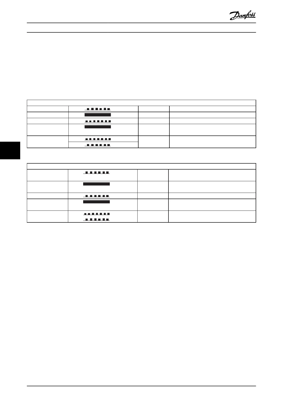
State LED Description
Standby Green: Flashing green The device needs commissioning
Device operational Green: Solid green The device is operational
Major recoverable fault Flashing red The device has detected a recoverable fault (MAR)
Major unrecoverable
fault
Red: Solid red The device has detected a un-recoverable fault
(MAU)
Self test
Red:
Flashing red/
green
The EIP option is in self-test mode
Green:
Table 7.1 MS: Module Status
State LED Description
No connections Green: Flashing green There are no established any CIP connections to
the device
Connected Green: Solid green There is established (at least) one CIP connection to
the device
Connection time-out Red: Flashing red One or more CIP connections has timed-out
Duplicate IP Red: Solid red The IP-address assigned to the device is already in
use
Self test
Red: Flashing red/
green
The EIP option is in self-test mode
Green
Table 7.2 NS1 + NS2: Network Status (one per port)
Check: Link Status
The status of the Ethernet link cannot be directly identified by means of the LEDs, if no CIP connection is established.
Use 12-10 Link Status to verify presents of the link.
Use 12-11 Link Duration to verify that the link is steady present.
The parameter will show the duration of the present link, and preset to 00:00:00:00 if the link is broken.
Check: Cabling
In rare cases of cabling mis-configuration, the option might show the presents of a link, but no communication is running.
Exchange the cable in doubt.
Check: IP Address
Verify that the option has a valid IP address (please refer to section: IP Settings) in 12-01 IP Address. If the option has
identified a duplicate IP Address NS LEDs will light steady red. If the option is set up for BOOTP or DHCP, verify that a
BOOTP or DHCP server is connected in 12-04 DHCP Server. If no server is connected, the parameter will show:
000.000.000.000.
7.1.2 Alarm Word and Warning Word
Alarm word and warning word are shown in the display in Hex format. If there is more than one warning or alarm, a sum of
all warnings or alarms will be shown. Warning word and alarm word are displayed in 16-90 Alarm Word to 16-95 Ext. Status
Word 2. For more information on the individual alarms and warnings, please refer to the frequency converter Design Guide.
Troubleshooting MCA 121 EtherNet/IP
38 MG.90.J3.02 - VLT
®
is a registered Danfoss trademark
77