Specifications
Description Units Minimum Maximum Comment
Power-up pin threshold Vdc 2 36 To wake up by cycling input power.
Power-up pin threshold Vdc 4.5 36 To wake up by digital input.
Power-up time delay mSec 250 500
SRon Minimum voltage rise
rate for power turn-
on
V/ms — — The voltage applied to the input pins must exceed
this value to guarantee the device will power-up.
Toff Turn-off time ms 150 400 From software commanded shutdown to micro
reset.
Sensor power supply ratings
PLUS+1
®
modules that support sensor inputs are provided with dedicated, software adjustable, regulated
sensor power supply and ground pins. Refer to individual product data sheets for sensor power supply
current ratings.
General
Description Comment
Short circuit to ground Output is not damaged and fault is detected.
Short circuit to battery + Output is not damaged and fault is detected.
Specifications
Description Units Minimum Maximum Comment
Output short circuit voltage Vdc 36
Sensor output voltage Vdc 3 12
Output current mA 0 500 The maximum power must be limited to 2.5 Watts for Vout
greater than 5 Vdc.
Output Load Capacitance µF 10
Hold up time after power loss ms 5 15
SC Controllers feature two additional levels of regulated power: 1.6 Vdc and 3.3 Vdc. The PLUS+1
®
GUIDE
application developer can detect open and short digital inputs, when these power supplies are used in
conjunction with DIN/AIN inputs.
Specifications
Description Units Minimum Maximum Comment
Output short circuit voltage Vdc 36
Output voltage, sensors Vdc 3 12 Sensor power supply drops below minimum if controller
power supply is less than 7 Vdc.
Output voltage, DIN diagnostics Vdc 1.58 1.76 Nominal 1.6
Output voltage, DIN diagnostics Vdc 3.21 3.45 Nominal 3.3
EEPROM Write/Erase ratings
To prevent unexpected memory writes, care must be taken to ensure memory with a high number of
read/write cycles is either U32 or S32 data types.
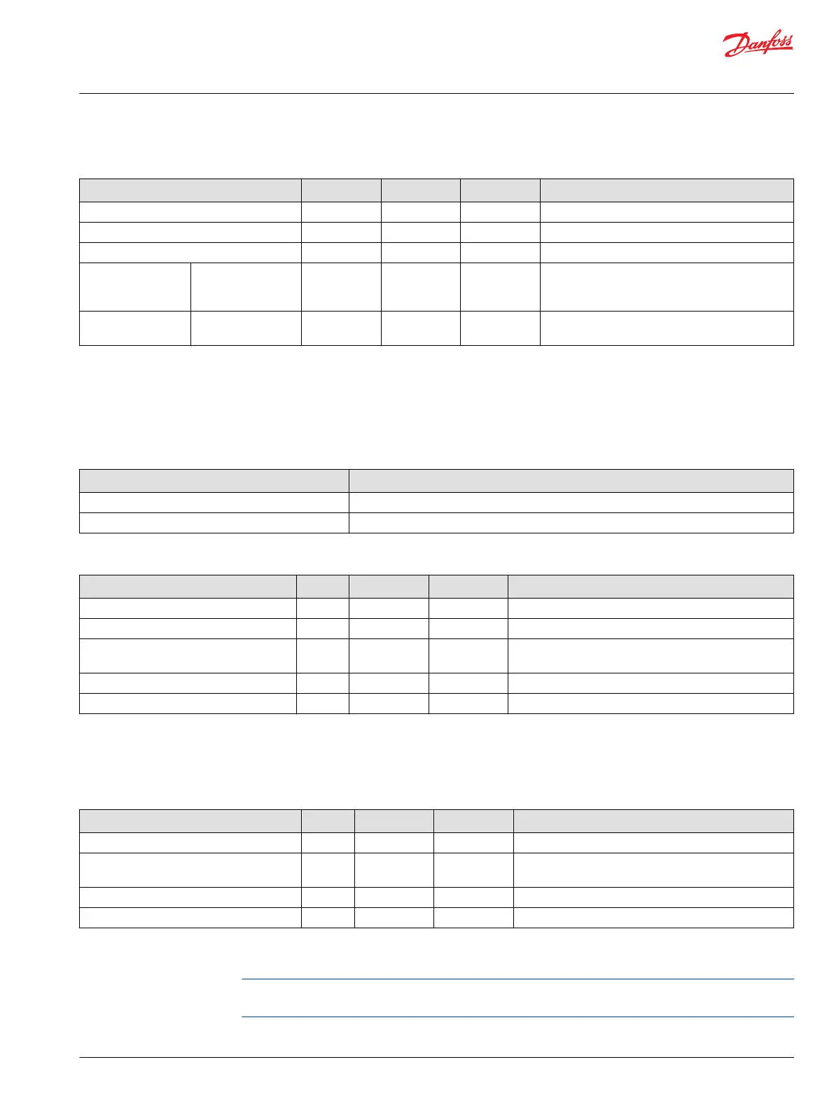
Technical Information
PLUS+1 SC0XX-1XX Controller Family
Product ratings
©
Danfoss | June 2016 L1415500 | BC00000235en-US0201 | 19
 Loading...