Specifications (continued)
Description Units Minimum Maximum Comment
Input impedance (pulled to 2.5 Vdc, low range) kΩ 7.2 7.4
Input impedance (no pull ups, low range) kΩ 230 236
Input impedance (pulled to 5 Vdc or ground, middle range) kΩ 13.9 14.3
Input impedance (pulled to 2.5 Vdc middle range) kΩ 7.2 7.4
Input impedance (no pull ups, middle range) kΩ 230 236
Input impedance (pulled to 5 Vdc or ground, high range) kΩ 13 13.4
Input impedance (pulled to 2.5 Vdc high range) kΩ 6.9 7.1
Input impedance (no pull ups, high range) kΩ 108 112
This table shows the rising and falling thresholds when the input is used as a frequency input.
Specifications
Description Units Minimum Maximum Comment
Rising voltage threshold (high range) Vdc 11.83 26.55 Voltage required for frequency input to read high.
Falling voltage threshold (high range) Vdc 5.61 18.89 Voltage required for frequency input to read low.
Rising voltage threshold (middle range) Vdc 1.78 3.92 Voltage required for frequency input to read high.
Falling voltage threshold (middle range) Vdc 0.84 2.79 Voltage required for frequency input to read low.
Rising voltage threshold (low range) Vdc 0.11 0.30 Voltage required for frequency input to read high.
Falling voltage threshold (low range) Vdc 0.04 0.22 Voltage required for frequency input to read low.
If the frequency goes to zero, the data will not decay over time, it will be updated once a new pulse is
seen, or times out. It is possible to monitor the count of pulses to know when the frequency reading is
updated.
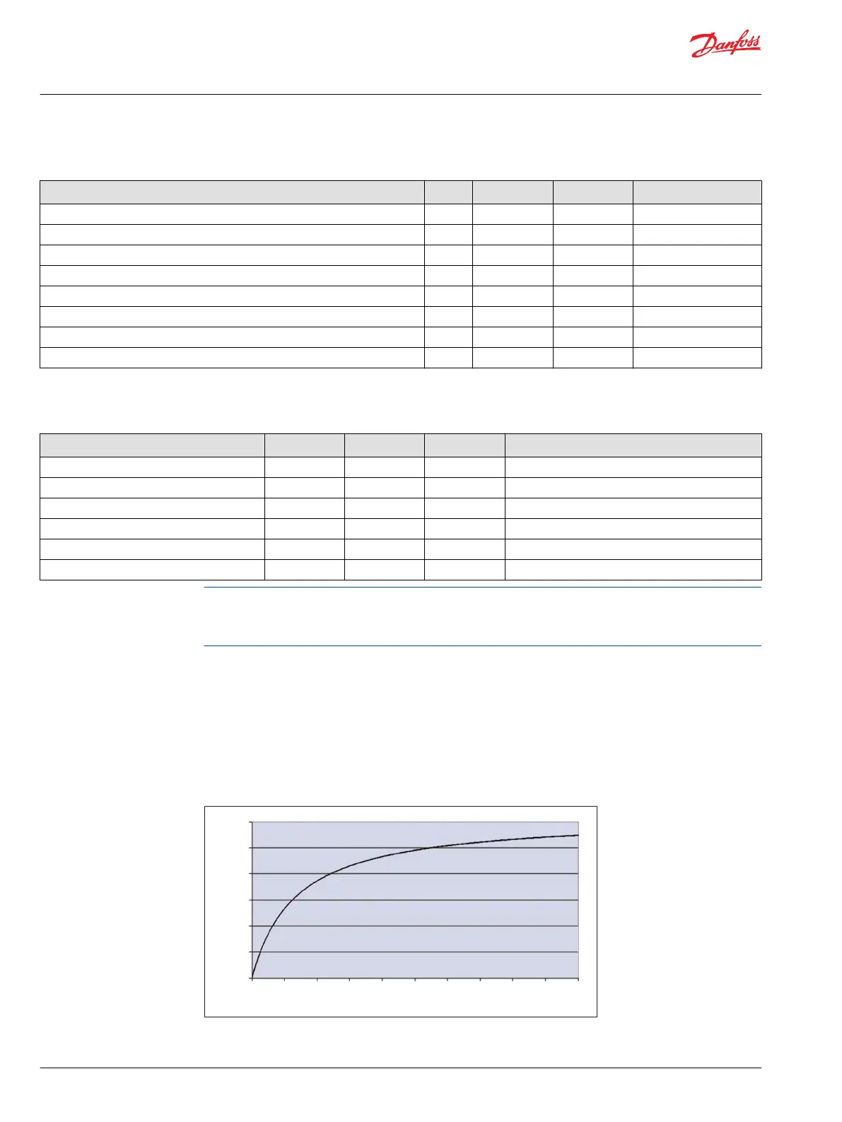
Digital/Analog/Resistance/4-20 mA Current (DIN/AIN/ResIN/CrntIN)
When a SC Controller input pin is configured as a resistance/rheostat/temp sensor input, the device will
provide up to 3.76 mA current to an external load (RL) which then can be measured. The equation for
relating AD counts to a given load is: AD counts = (30996*RL) / (RL + 1322). This calculation is solved
internally and the ohms value is available for the programmer. The following Rheostat inputs chart shows
the relationship between AD counts and load resistance in ohms.
Rheostat inputs chart
0
5000
10000
15000
20000
25000
30000
100009000
800070006000
500040003000
2000
10000
Load Resistance (Ω)
AD Counts
P200 083
Technical Information
PLUS+1 SC0XX-1XX Controller Family
Inputs
10 |
©
Danfoss | June 2016 L1415500 | BC00000235en-US0201
 Loading...