i.e. it is possible to turn off the control word if you do
not wish to use it in connection with updating or reading
parameters.
Bit 11, Relay 01:
Bit 11 = “0” Relay not activated.
Bit 11 = “1” Relay 01 activated, provided Control word
bit has been chosen in parameter 323.
Bit 12, Digital output, terminal 46:
Bit 12 = “0” Digital output has not been activated.
Bit 12 = “1” Digital output has been activated, provided
Control word bit has been chosen in parameter 341.
Bit 13/14, Selection of Setup:
Bits 13 and 14 are used to choose from the four menu
Setups according to the following table:
Setup
Bit 14 Bit 13
1 0 0
2 0 1
3 1 0
411
The function is only possible when Multi-Setups is se-
lected in parameter 004 Active Setup .
Note: I parameter 507 Selection of Setup a selection is
made to define how Bit 13/14 gates with the corre-
sponding function on the digital inputs.
Bit 15 Reversing:
Bit 15 = '0' causes no reversing.
Bit 15 = '1' causes reversing.
Note: In the factory setting reversing is set to digital in
parameter 506 Reversing. Bit 15 only causes reversing
when either Ser. communication , Logic or or Logic
and is selected.
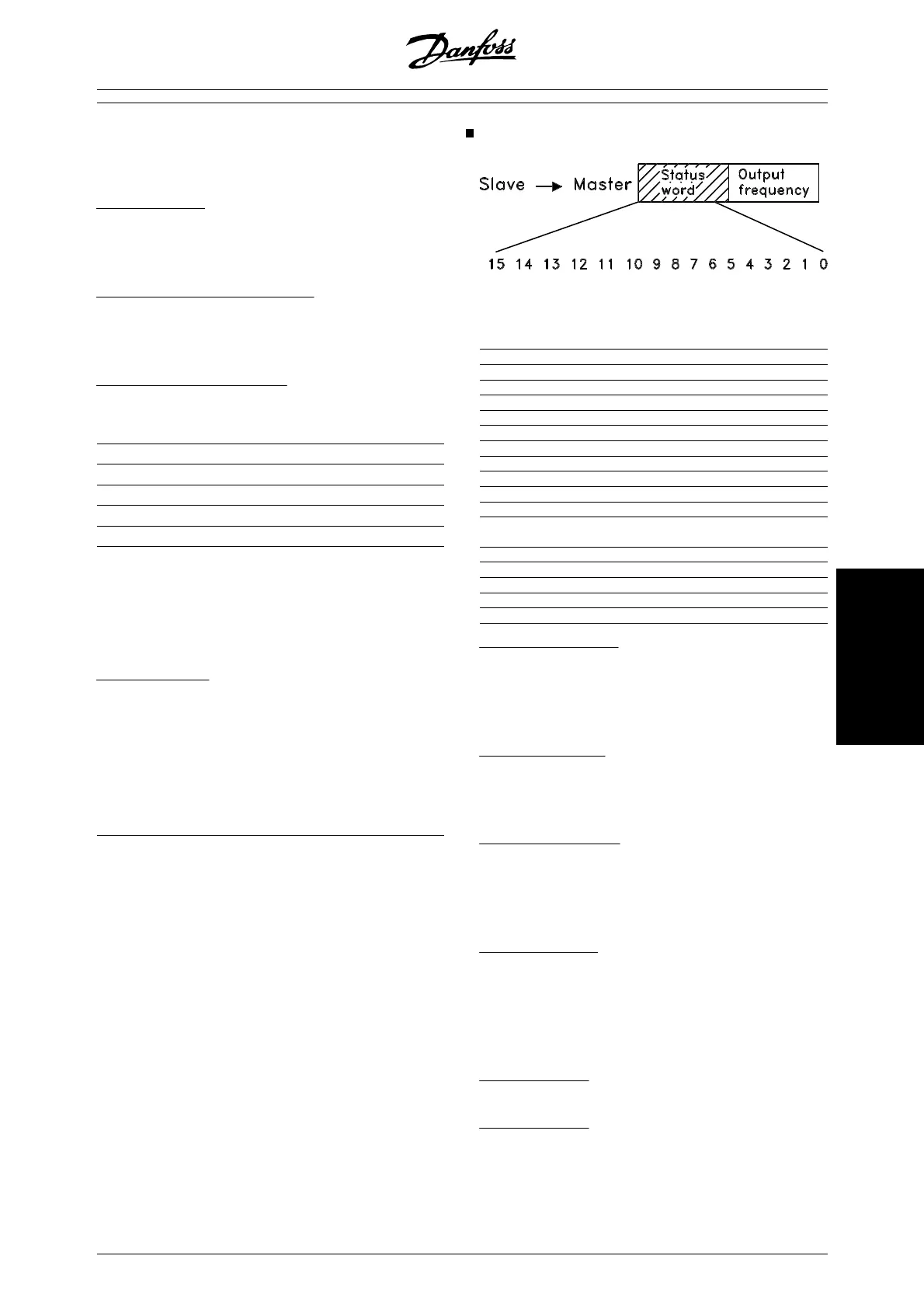
Status Word according to FC Profile
The status word is used to inform the master (e.g. a
PC) of the slave's (frequency converter) mode.
Slave•Master.
Bit Bit = 0 Bit =1
00 Control ready
01 Drive ready
02 Coasting stop
03 No trip Trip
04 Not used
05 Not used
06 Trip lock
07 No warning Warning
08 Speed • ref. Speed = ref.
09 Local control Ser. communi.
10 Outside
frequency range
Frequency limit
OK
11 Motor running
12
13 Voltage warn.
14 Current limit
15 Thermal warn.
Bit 00, Control ready:
Bit 00 = '1'. The frequency converter is ready for op-
eration.
Bit 00 = '0'. The frequency converter is not ready for
operation.
Bit 01, Drive ready:
Bit 01 = '1'. The frequency converter is ready for op-
eration, but there is an active coasting command via
the digital inputs or via serial communication.
Bit 02, Coasting stop:
Bit 02 = '0'. The frequency converter has released the
motor.
Bit 02 = '1'. The frequency converter can start the mo-
tor when a start command is given.
Bit 03, No trip/trip:
Bit 03 = '0' means that the frequency converter is not
in fault mode.
Bit 03 = '1' means that the frequency converter is trip-
ped, and that it needs a reset signal for operation to be
reestablished.
Bit 04, Not used:
Bit 04 is not used in the status word.
Bit 05, Not used:
Bit 05 is not used in the status word.
MG.27.E2.02 - VLT is a registered Danfoss trademark 117
Programming