Setup 2 contains the following preset references:
Par. 215 Preset reference 1 = 40.00%
Par. 216 Preset reference 2 = 50.00%
Par. 217 Preset reference 3 = 70.00%
Par. 218 Preset reference 4 = 100.00%
This table shows what the output frequency is:
Preset ref.,
msb
Preset ref.,
lsb
Selection of
Setup
Output frequency
[Hz]
0 0 0 2.5
0 1 0 5
1 0 0 10
1 1 0 17.5
0 0 1 20
0 1 1 25
1 0 1 35
1 1 1 50
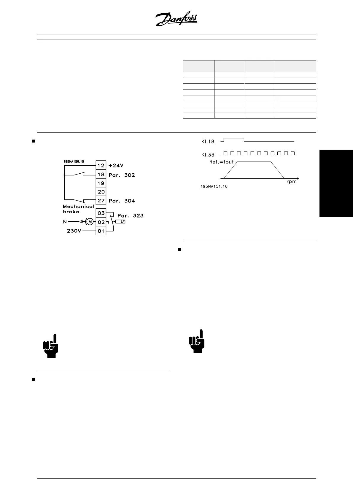
Connection of mechanical brake
Use of the relay for 230V AC brake
Par. 302 Digital input = Start [7]
Par. 304 Digital input = Coasting stop inver-
ted [2]
Par. 323 Relay output = Mechanical brake
control [25]
Mechanical brake control [25] = '0' => Brake is closed.
Mechanical brake control [25] = '1' => The brake is
open.
See more detailed parameter settings under Control of
mechanical brake .
NB!
Do not use the internal relay for DC brakes
or brake voltages > 250 V.
Counter stop via terminal 33
The start signal (terminal 18) must be active, i.e. logical
'1', until the output frequency is equal to the reference.
The start signal (terminal 18 = logical '0') must then be
removed before the counter value in parameter 344
has managed to stop the VLT frequency converter.
Par. 307 Digital input = Pulse input [30]
Par. 343 Precise stop function = Counter stop
with reset [1]
Par. 344 Counter value = 100000
Use of internal PID-controller - closed loop proc-
ess control
1. Connect the frequency converter to mains
and motor cables as usual.
2. Connect transmitter (feedback signal) to +
terminal 12 and - terminal 60 (applies to 2-
wire transmitters 4-20 mA). (Connect trans-
mitters with 0-10 V DC to + terminal 53 and -
terminal 55).
NB!
Connect terminal 55 as - and terminal 60
as + for current signal (0/4-20 mA) and
terminal 53-55 for voltage signal (0-10 V
DC) if transmitters with separate voltage
supply are used.
3. Connect the start signal between terminal 12
and 18, 12-27 must be connected or set to no
function (parameter 304 = 0).
4. Set all parameters in the Quick Menu and
enter the Main Menu (to enter the Main Menu:
Press Quick Menu and + simultaneously).
5. Set the following parameters:
100 = Process controller closed loop [3]
MG.27.E2.02 - VLT is a registered Danfoss trademark 57
Installation