101 = Variable torque medium [3]
If used with centrifugal pumps and fans.
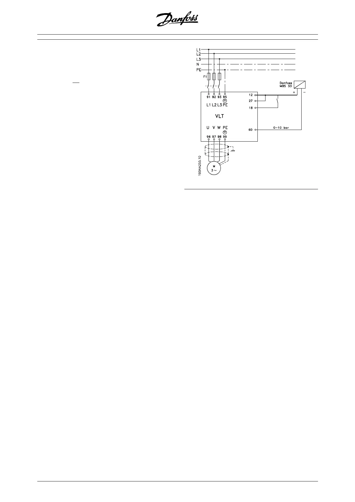
308 = Feedback [2] (for 0-10 V DC transmit-
ters)
or
314 = Feedback [2] (for 4-20 mA transmitters)
414 = Minimum feedback scaling, must be
set to the minimum feedback value
415 = Maximum feedback scaling, must be
set to the maximum feedback value
Example: Pressure transmitter 0-10 bar: 414
= 0 and 415 = 10
416 = Process units: As shown on the local
control panel (example: bar [4])
437 = Normal [0]: The output frequency
should be reduced when the feedback signal
increases
Inverse [1]: The output frequency should in-
crease when the feedback signal increases
440 = Proportional gain (P-gain) 0.3-1.0 (ex-
perienced value)
441 = Integration time (I-time) 3-10 sec. (ex-
perienced value)
442 = Differentiation time (D-time) 0-10 sec.
(experienced value)
205 = Max. reference is to be set equal to
parameter 415 (example: 10 bar)
215 = Preset reference 1. Set the preset ref-
erence to the wanted min. reference value
(example: 5 bar)
(Parameter 205 and 215 are shown in the
process unit chosen in parameter 416).
The value in brackets [ ] are data values cor-
responding to the wanted function. Example:
Parameter 308 Feedback signal = [2]
If the motor is supposed to always run at a
minimum speed, a such can be selected in
parameter 204 = output frequency low limit.
(For pump works it is typically 15-20 Hz).
With the above connections and settings all
normal pump and fan applications will work
properly. In certain cases it might be neces-
sary to optimize the PID-controllerr (parame-
ter 440, 441 and 442) beyond the mentioned
experienced values.
58 MG.27.E2.02 - VLT is a registered Danfoss trademark