VLT
®
Series 3500
78
★ = ROM default setting. ✔ = Normal Danfoss setup. Text in ( ) = display text. Figures in [ ] are used when communicating with the bus.
403 Terminal 19 (INPUT 19), continued
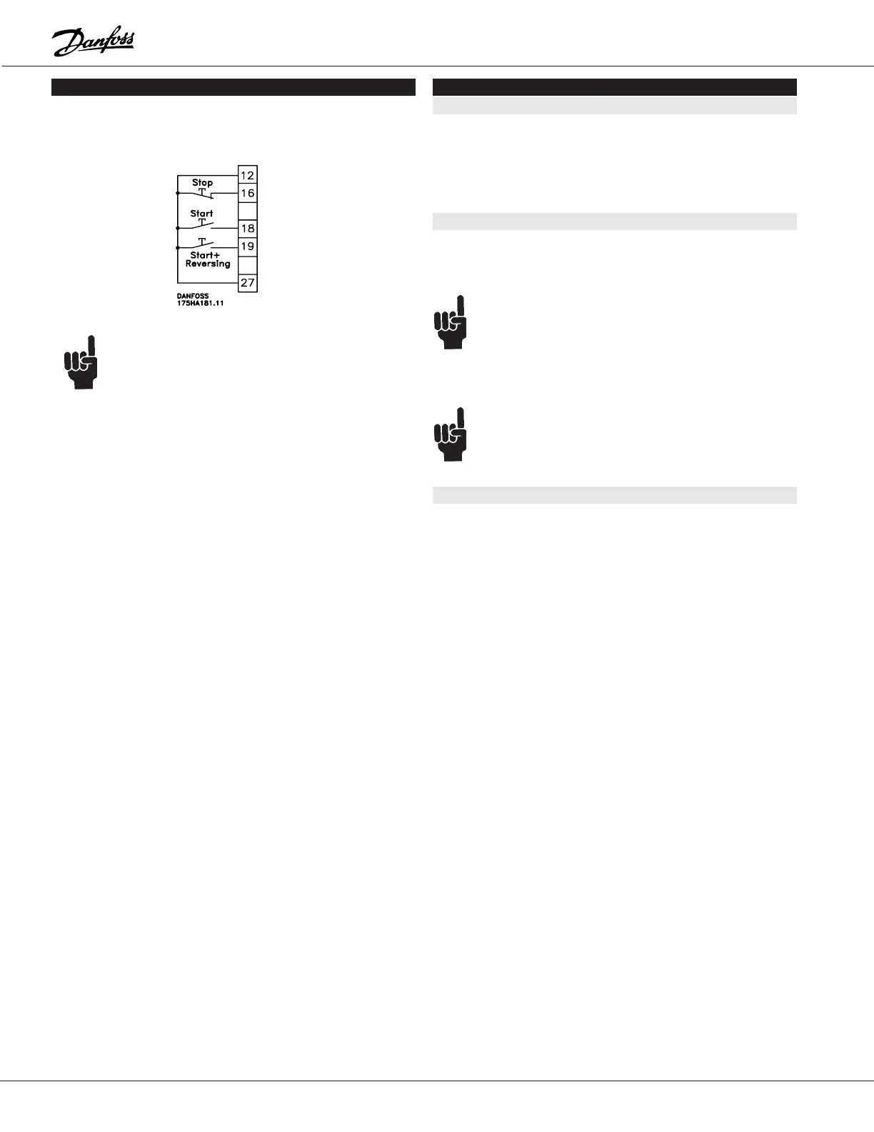
Start with reversing
[1] and parameter
402 Latch Start
[1]:
If a latch start has been selected in parameter 402, reverse
will also latch start.
NOTE:
If 24 V DC is supplied from terminal 12 to termi-
nals 18 and 19 at the same time, the motor will
stop.
No operation
[2]:
Same as parameter 402.
External H-O-A Hand
[3]:
Select if the H-O-A function is to be used externally from
the drive to switch between manual operation (Hand) and
the normal remote control (Auto). By applying 24 V DC from
terminal 12 to terminal 16, the manual operation mode is
activated and the output frequency can be adjusted by the
reference selected as external manual operation in param-
eter 420.
Latch Start Hand
[4]:
Selected for starting the inverter when the drive is in the
manual operation mode, “Hand”. When 24 V DC is supplied
from terminal 12 to terminal 19 for a minimum of 20 msec.,
start will be activated.
404 Terminal 27 Stop (INPUT 27)
Value:
★ Motor coasting stop (MTR. COAST) [0]
Quick-stop (Q-STOP) [1]
DC braking (DC-BRAKE) [2]
Reset and motor coasting stop (RST&COAST) [3]
Stop (STOP) [4]
Function:
Used to choose between different possible functions of ter-
minal 27.
NOTE:
The motor is only able to run in remote mode if 24 V
DC is supplied from terminal 12 to terminal 27. This
can be overridden by using serial communication or
local mode.
NOTE:
in order to allow the opening of the circuit to stop
the drive in Local/Hand mode, parameter 003 must
be set to KEY HOA w. stp and parameter must be
set to either MTR. COAST or RST & COAST.
Description of choice:
Motor coasting stop
[0]:
Choose if the motor is to coast to rest. When the connec-
tion from terminal 12 (24 V DC) to terminal 27 is broken, the
motor will coast to a stop.
Quick-stop
[1]:
Select if the motor is to be stopped using the alternative
ramp time selected in parameter 218. When the connection
from terminal 12, 24 V DC, to terminal 27 is broken, the mo-
tor will decelerate to a stop using the alternative decelera-
tion time.
DC braking
[2]:
Select if the motor is to be stopped using DC braking which
is set up in parameters 306, 307 and 308. This function is
only active when the values in parameters 306 and 308 are
different from 0. When the connection from terminal 12 (24
V DC) to terminal 27 is broken, the motor will stop with DC
braking.
Reset and coasting stop
[3]:
Select if coast to stop and reset (see description of reset in
parameters 400 and 401) are desired at the same time.
When the connection from terminal 12 (24 V DC) to termi-
nal 27 is broken, the motor will coast to stop and reset.
Stop
[4]:
Choose if it is desired to stop the drive using the decel
ramp as defined by parameter 216. When the connection
from terminal 12 (24 V DC) to terminal 27 is broken, the
drive decelerates to a stop as defined by parameter 216.
 Loading...
