VLT
®
Series 3500
91
Bit 15,
TIMERS OK/OVERSHOOT:
Bit 15 = “0” means that the timers for thermal motor protec-
tion and thermal drive protection have not exceeded 100%.
Bit 15 = “1” means that one of the timers has exceeded
100%.
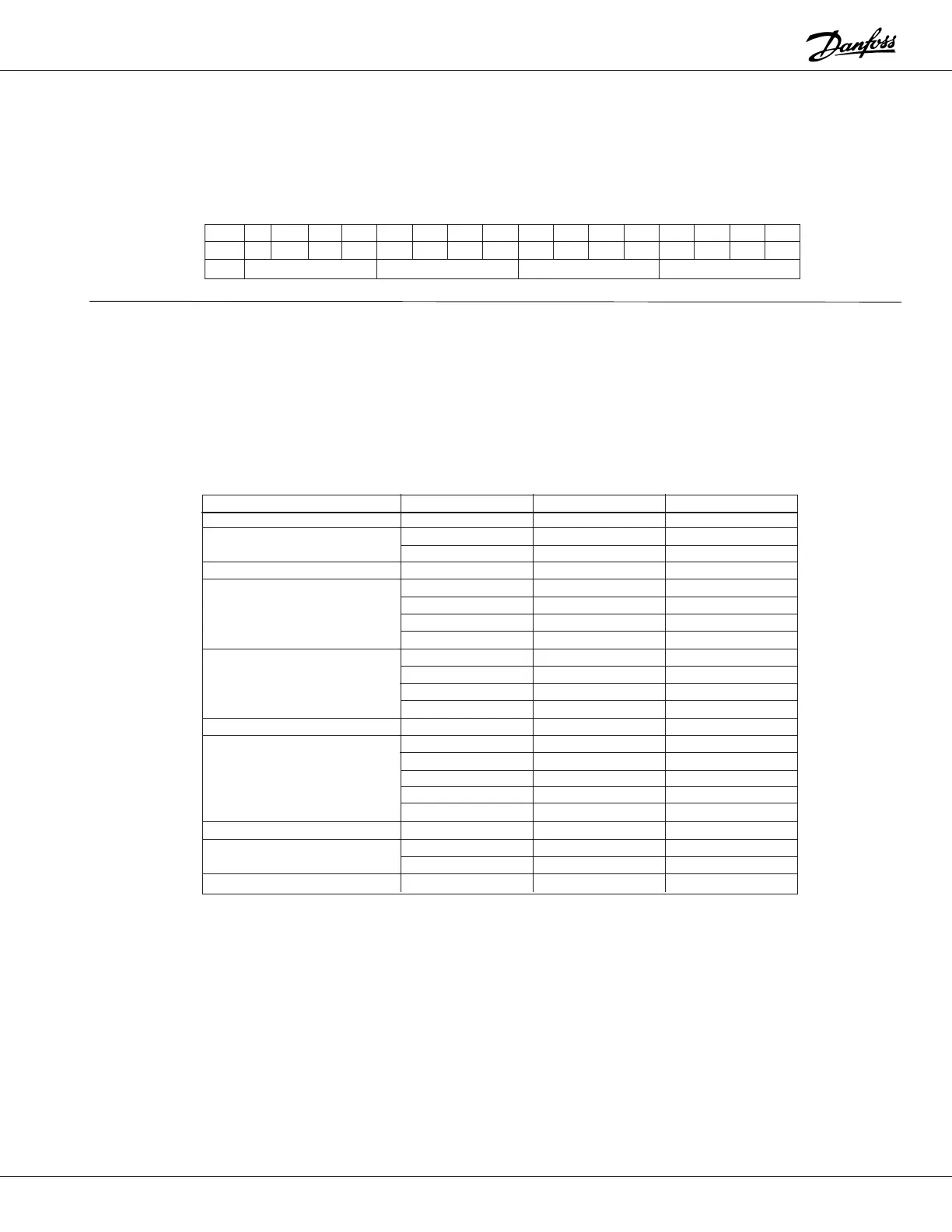
Address
Control/status word
Data value
Check-sum
Check-sum: bytes 2-19 = 1007, reduced to 07.
Parameter no.
Example:
The status word below says that the motor is running on
the desired speed reference, but outside the defined fre-
quency area. Consequently, bit 10 = “0” (out of frequency
range) and bit 07 = “1” (warning). Voltage, current and tim-
ers are OK.
Message Example:
A drive, with address 1, is to be given a start signal and a
speed reference that corresponds to 40 Hz.
A start signal is given by means of the control word and the
speed reference is given to parameter 516, bus reference,
80% corresponding to 40 Hz, since the maximum frequency
is 50 Hz. This results in the following message:
Message from the master (PC or PLC) to the frequency converter
Function Byte Number ASCII Character Decimal Value
Start-byte 1 < 60
2048
3149
Control character 4 U 85
5O79
6G71
7D68
8@64
9048
10 5 53
11 1 49
12 6 54
Sign 13 + 43
14 0 48
15 0 48
16 0 48
17 8 56
18 0 48
Decimal point 19 0 48
20 0 48
21 7 55
Stop-byte 22 > 62
Bit 15 14 13 12 11 10 09 08 07 06 05 04 03 02 01 00
0/10000101110000111
ASCII @ K H G
 Loading...
