7-16
VLT is a registered Danfoss trademark
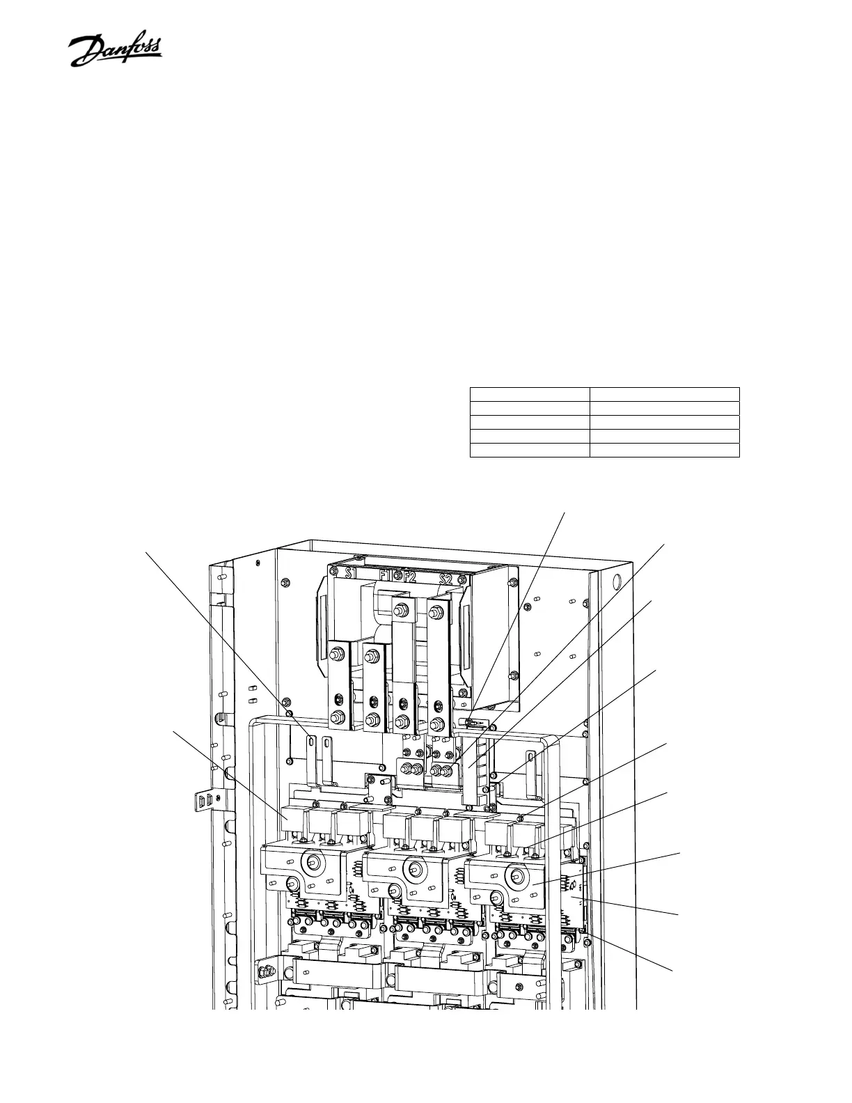
Figure 7-12. IGBT Modules (4 of 4)
15. Remove 18 retaining screws (T30) on IGBT input
terminals. Note snubber capacitors come off
when screws are removed. There are 6 screws
for each IGBT module.
16. Remove 2 retaining nuts (8 mm) connecting each
IGBT-Cap bus bar assemblies to IGBT-Ind bus bar
assembly and remove the IGBT-Cap bus bar
assembly. There are three IGBT-Cap bus bar
assemblies.
17. Remove retaining nut (8 mm) from high frequency
board.
18. Remove 2 retaining screws (T25) from high
frequency board.
19. Disconnect wire assembly from high frequency
board and remove board.
20. If unit has Brake IGBTs, remove the 4 retaining
screws (T30) connecting IGBT-Ind bus bar
IGBT-Cap bus bar BB47
Retaining screw
(Step 15)
Snubber capacitor
assembly to Brake IGBT. Note that there are 2
screws per Brake IGBT module.
21. Remove 4 retaining nuts (13 mm) connecting
IGBT-Ind bus bar assembly to two DC bus bars
from inductor. Remove IGBT-Ind bus bar
assembly.
22. Remove 8 retaining screws (T25) mounting each
IGBT module.
REASSEMBLY
1. Replace IGBT modules in accordance with
instructions included with replacement modules.
2. Reassemble in reverse order.
Retaining nut
(Step 16)
High frequency
board
IGBT board
Retaining nut
(Step 17)
Retaining screw
(Step 18)
Retaining screw (brake IGBT option)
(Step 20)
Retaining nut
(Step 21)
IGBT retaining screw
(Step 22)
Attaching Hardware Tightening Torque
8 mm / T25 20 in-lbs (2.25 Nm)
10 mm / T30 35 in-lbs (4.0Nm)
13 mm 85 in-lbs (9.6 Nm)
17 mm / T50 170 in-lbs ( 19.2 Nm)
 Loading...
