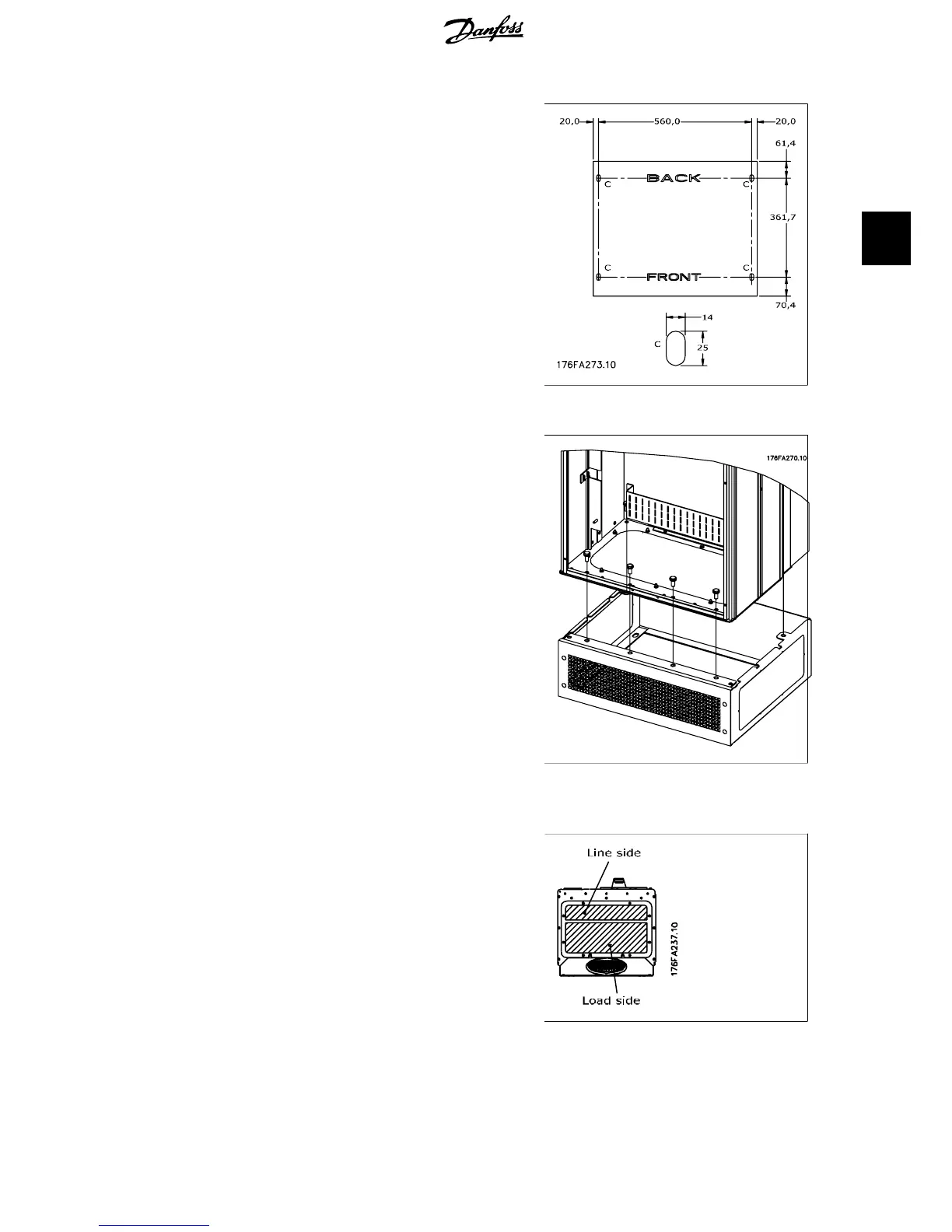
The E1 enclosure is always delivered with a
pedestal as standard. Install the pedestal on
the floor. Fixing holes are to be drilled accord-
ing to this figure:
Illustration 3.20: Drill master for fixing holes in
floor.
Mount the drive on the pedestal and fix it with
the included bolts to the pedestal as shown on
the illustration.
Illustration 3.21: Mounting of drive to pedestal
3.1.6. Gland/Conduit Entry - IP21 (NEMA 1) and IP54 (NEMA12)
Cables are connected through the gland plate
from the bottom. Remove the plate and plan
where to place the entry for the glands or
conduits. Prepare holes in the marked area on
the drawing.
The gland plate must be fitted to the frequen-
cy converter to ensure the specified protection
degree, as well as ensuring proper cooling of
the unit. If the gland plate is not mounted, it
may trip the unit.
Illustration 3.22: Cable entry viewed from the bot-
tom of the frequency converter - Enclosure D1 and
D2.
VLT
®
5000/6000/8000
High Power Installation Guide
3. Installation
MI.90.J2.02 - VLT
®
is a registered Danfoss trademark
21
3
 Loading...


