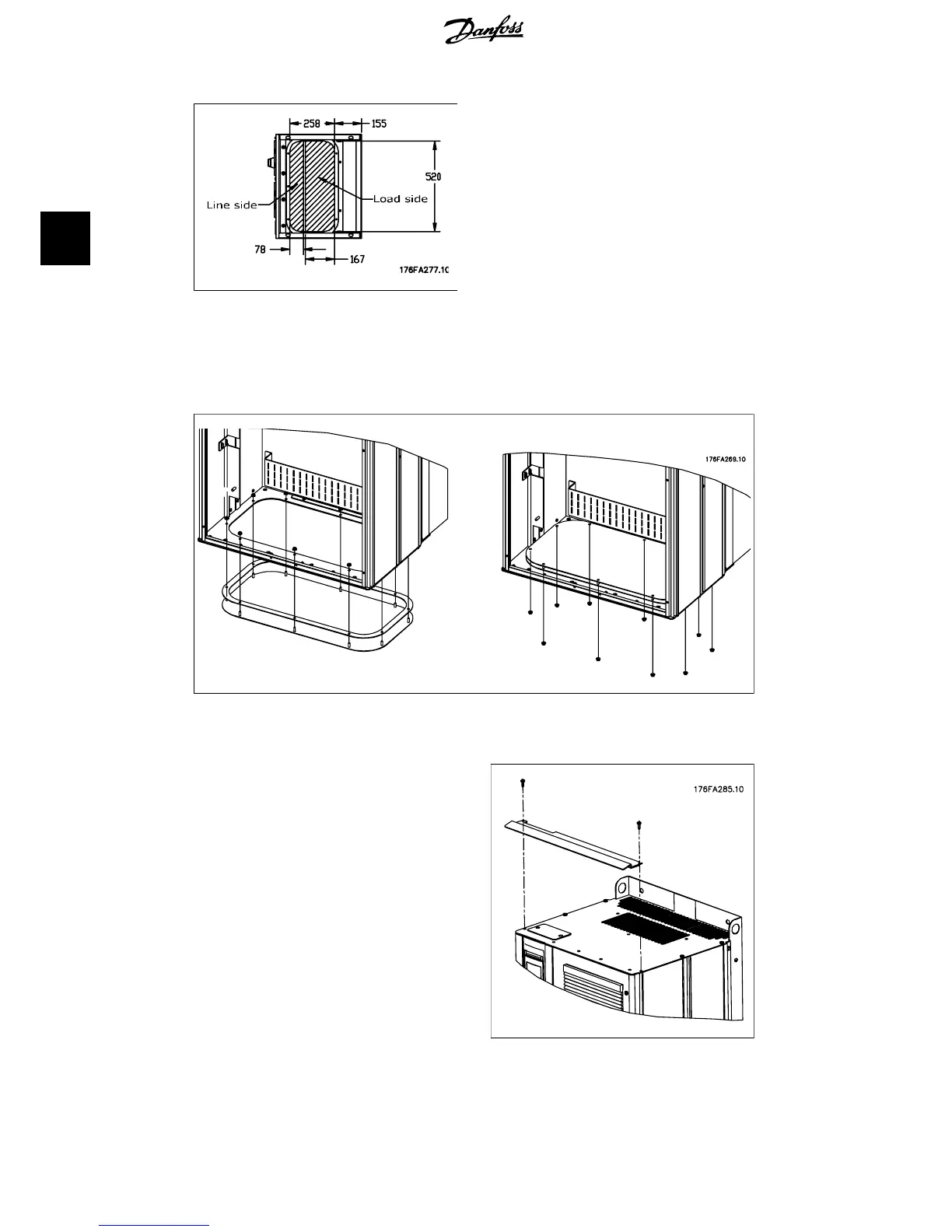
Illustration 3.23: Cable entry seen from the bot-
tom of the frequency converter - Enclosure E1.
The bottom plate of the E1 enclosure can be mounted from either in or outside of the enclosure,
allowing flexibility in the installation process, i.e. if mounted from the bottom the glands and cables
can be mounted before the frequency converter is placed on the pedestal.
Illustration 3.24: Mounting of bottom plate, E1 enclosure.
3.1.7. IP21 Drip shield installation (D1 and D2 enclosure)
To comply with the IP21 rating, a separate
drip shield is to be installed as explained be-
low:
• Remove the two front screws
• Insert the drip shield and replace
screws
• Torque the screws to 5,6 Nm (50 in-
lbs)
Illustration 3.25: Drip shield installation.
3. Installation
VLT
®
5000/6000/8000
High Power Installation Guide
22
MI.90.J2.02 - VLT
®
is a registered Danfoss trademark
3
 Loading...


