5. Installation on Pedestal - IP 21 / IP 54 Units
The frequency converter can also be installed on the floor. A dedicated floor stand is designed for
that purpose. It can only be used for units produced after week 50, 2004 (serial number
XXXXXG504).
This section describes the installation of a pedestal unit available for the VLT series frequency
converters frames D1 and D2. This is a 200 mm high pedestal that allows these frames to be floor
mounted. The front of the pedestal has openings for input air to the power components.
The frequency converter gland plate must be installed to provide adequate cooling air to the
control components of the frequency converter via the door fan and to maintain the IP21/NEMA
1 or IP54/NEMA 12 degrees of enclosure protections.
There is one pedestal that fits both frames D1 and D2.
Required Tools
Required Tools:
• Socket wrench with 7-17 mm sockets
• T30 Torx Driver
Torques:
• M6 - 4.0 Nm (35 in-lbs)
• M8 - 9.8 Nm (85 in-lbs)
• M10 - 19.6 Nm (170 in-lbs)
Kit Contents:
• Pedestal parts
• Instruction manual
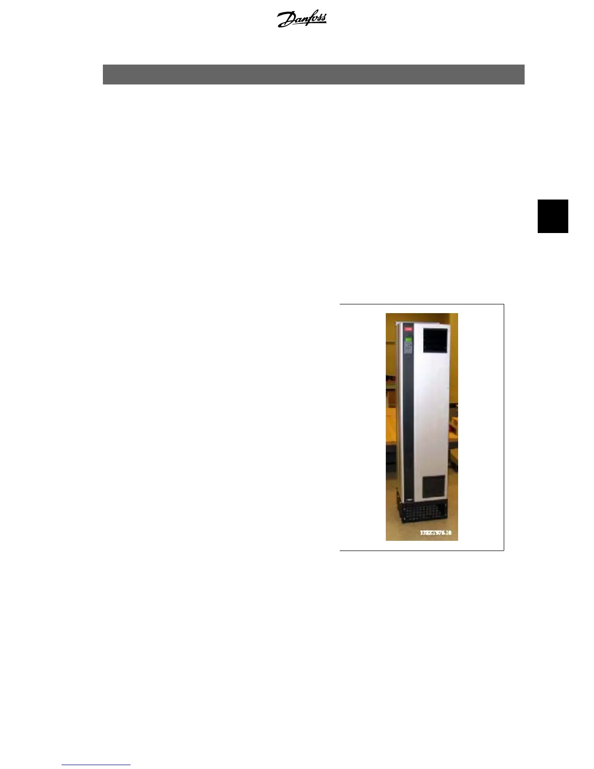
Illustration 5.1: Drive on pedestal.
VLT
®
5000/6000/8000
High Power Installation Guide
5. Installation on Pedestal - IP 21 / IP 54 Units
MI.90.J2.02 - VLT
®
is a registered Danfoss trademark
43
5
 Loading...


