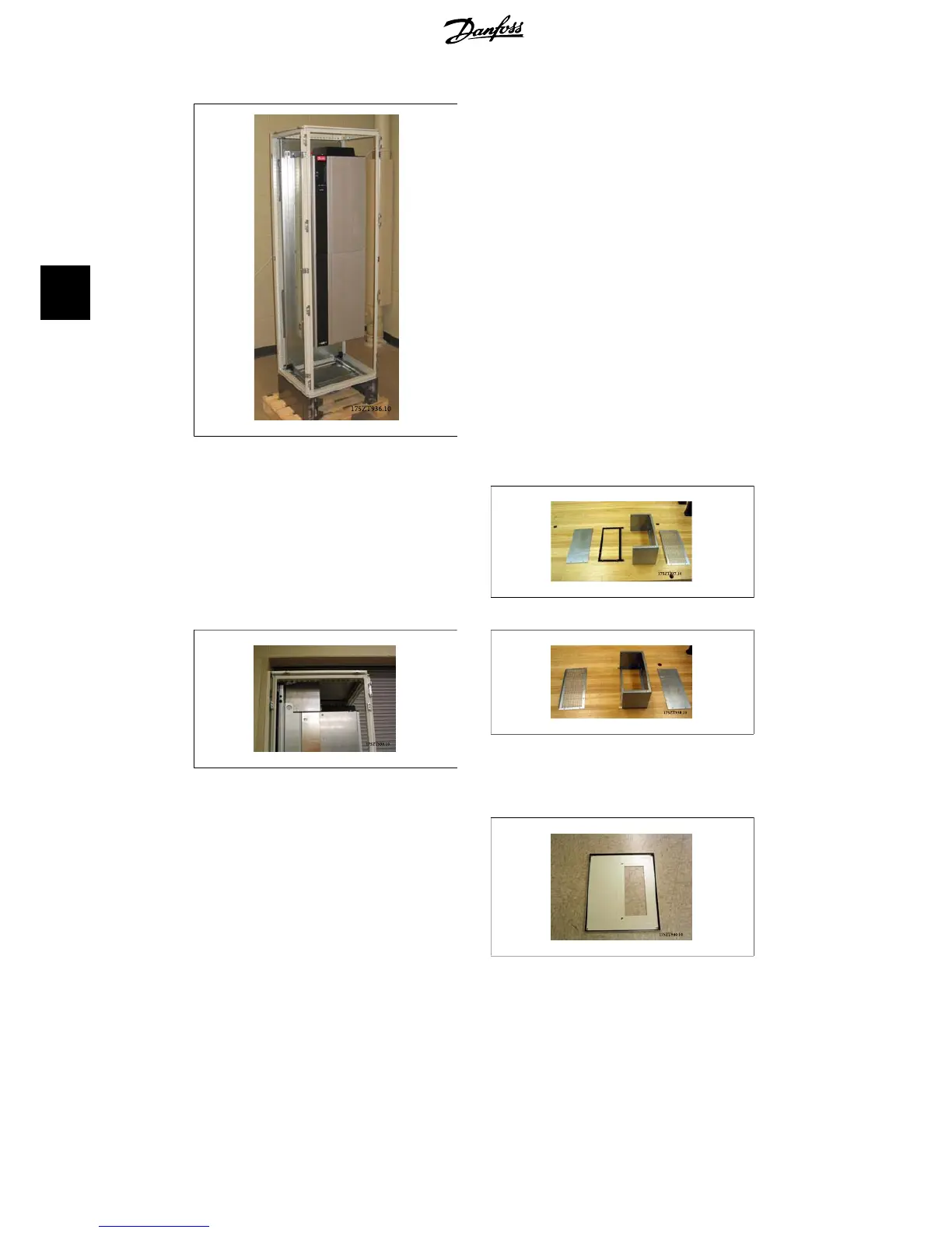
Illustration 4.8: Frequency converter installed in
cabinet
The top ductwork cover is composed of the
following pieces as shown below. From left to
right: 1. top duct closing plate, 2. frequency
converter bracket, 3. duct, 4. duct vented top
cover.
Illustration 4.9: Top duct assembly
Illustration 4.10: Top duct work and enclosure top
installed
Illustration 4.11: The top duct work partially as-
sembled with frequency converter bracket
Temporarily install the top duct section as
shown above. Use the top duct cover piece to
mark the enclosure top for the opening.
Alternatively the mounting template (supplied
drawing) can be used to make the enclosure
cut-out.
Illustration 4.12: Rittal enclosure top with cutout
Standard Rittal enclosures top is cut. Gasket is not
used on the cutout. Gasket is part of duct work.
4. Duct Work Cooling Kit for IP00 Units
VLT
®
5000/6000/8000
High Power Installation Guide
38
MI.90.J2.02 - VLT
®
is a registered Danfoss trademark
4
 Loading...


