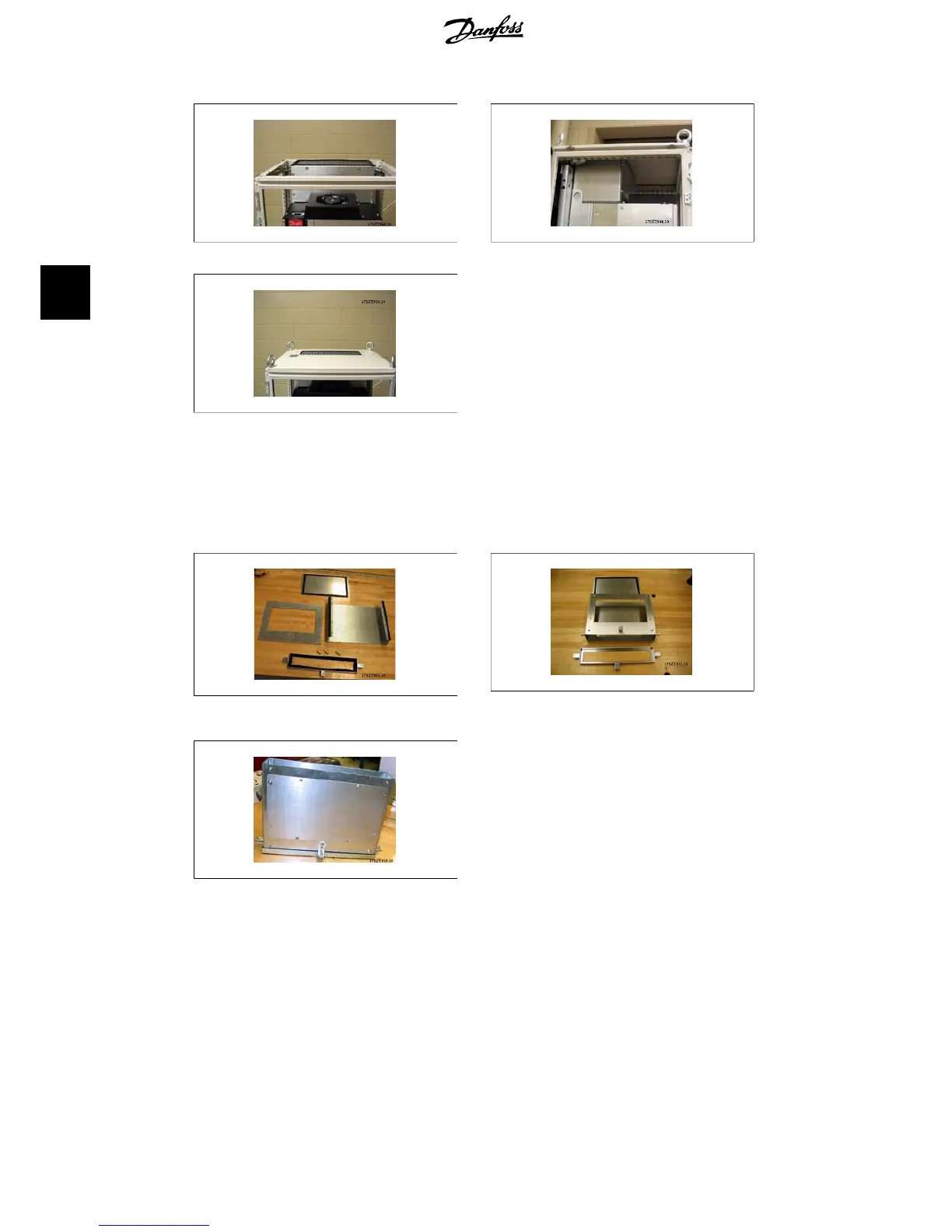
Illustration 4.20: Top duct closing plate installed Illustration 4.21: Enclosure top installed
Illustration 4.22: Top view of Rittal enclosure
The bottom duct assembly pieces. Refer to drawing showing exploded view of duct work compo-
nents. Gasket is installed as shown. Assemble the bottom duct less the cover. Assembly includes
the mounting of 3 angle brackets on the front and sides of the partially assembled bottom duct.
The bottom duct collar is bolted to the duct using 3 - T25 screws in the outermost holes of the
brackets. Tighten the screws to compress the gasket.
Illustration 4.23: Bottom ductwork pieces
Illustration 4.24: Bottom ductwork partially as-
sembled
Illustration 4.25: Completely assembled bottom
duct work
The duct assembly is used to mark the bottom
cutout. Temporarily install the bottom duct
work as shown to the right. Use the inside of
the ductwork to mark the bottom of the en-
closure for the opening.
4. Duct Work Cooling Kit for IP00 Units
VLT
®
5000/6000/8000
High Power Installation Guide
40
MI.90.J2.02 - VLT
®
is a registered Danfoss trademark
4
 Loading...


