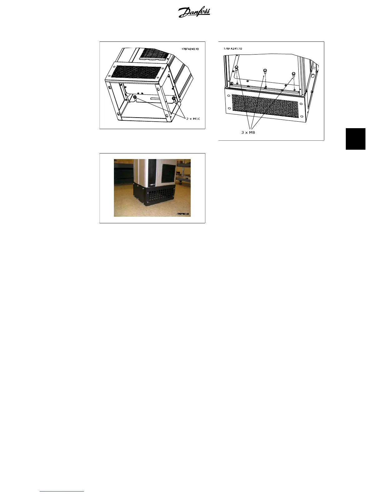
Illustration 5.6: Two nuts at rear side.
Illustration 5.7: Three front screws.
Illustration 5.8: Frame D2 with pedestal installed
VLT
®
5000/6000/8000
High Power Installation Guide
5. Installation on Pedestal - IP 21 / IP 54 Units
MI.90.J2.02 - VLT
®
is a registered Danfoss trademark
45
5
 Loading...


