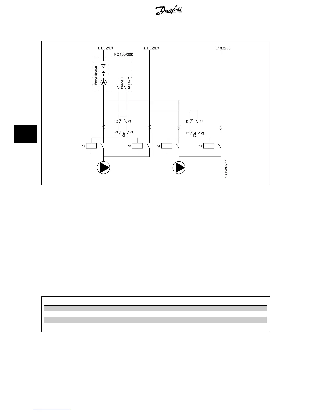
6.1.12 Lead Pump Alternation Wiring Diagram
Every pump must be connected to two contactors (K1/K2 and K3/K4) with a mechanical interlock. Thermal relays or other motor protection devices must
be applied according to local regulation and/or individual demands.
• RELAY 1 (R1) and RELAY 2 (R2) are the built-in relays in the frequency converter.
• When all relays are de-energized, the first built in relay to be energized will cut in the contactor corresponding to the pump controlled by the
relay. E.g. RELAY 1 cuts in contactor K1, which becomes the lead pump.
• K1 blocks for K2 via the mechanical interlock preventing mains to be connected to the output of the frequency converter (via K1).
• Auxiliary break contact on K1 prevents K3 to cut in.
• RELAY 2 controls contactor K4 for on/off control of the fixed speed pump.
• At alternation both relays de-energizes and now RELAY 2 will be energized as the first relay.
6.1.13 Start/Stop Conditions
Commands assigned to digital inputs. See
Digital Inputs
, par.5-1*.
Variable speed pump (lead) Fixed speed pumps
Start (SYSTEM START /STOP) Ramps up (if stopped and there is a demand) Staging (if stopped and there is a demand)
Lead Pump Start Ramps up if SYSTEM START is active Not affected
Coast (EMERGENCY STOP) Coast to stop Cut out (built in relays are de-energized)
Safety Interlock Coast to stop Cut out (built in relays are de-energized)
Function of buttons on Local Control Panel
6 Application Examples VLT
®
AQUA Drive Design Guide
166
MG.20.N5.02 - VLT
®
is a registered Danfoss trademark
6
 Loading...


