[6] ETR trip 2
[7] ETR warning 3
[8] ETR trip 3
[9] ETR warning 4
[10] ETR trip 4
Select
ETR Warning 1-4
, to activate a warning on the display when the motor is overloaded.
Select
ETR Trip 1-4
to trip the adjustable frequency drive when the motor is overloaded.
Program a warning signal via one of the digital outputs. The signal appears in the event of a warning and if the adjustable frequency drive trips (thermal
warning).
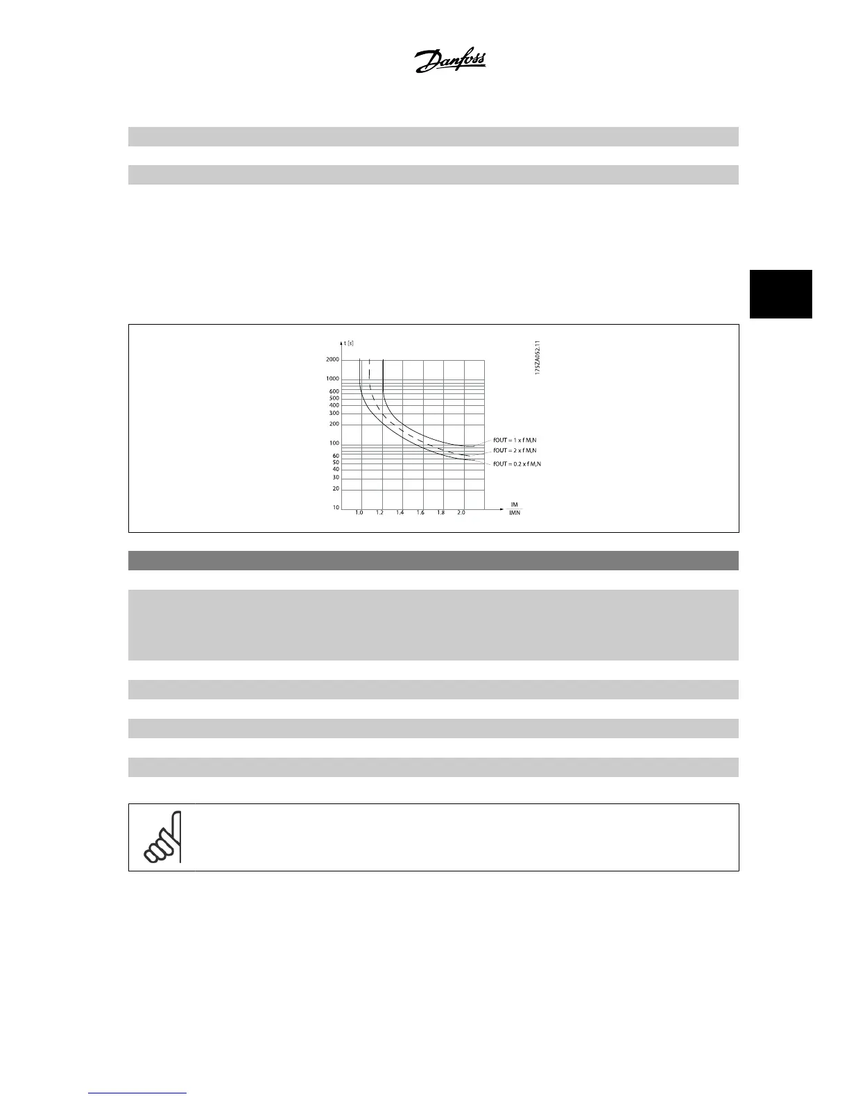
ETR (Electronic Terminal Relay) functions 1-4 will calculate the load when the set-up where they were selected is active. For example, ETR starts calculating
when set-up 3 is selected. For the North American market: The ETR functions provide class 20 motor overload protection in accordance with NEC.
1-93 Thermistor Source
Option: Function:
Select the input to which the thermistor (PTC sensor) should be connected. An analog input option
[1] or [2] cannot be selected if the analog input is already in use as a reference source (selected in
par. 3-15
Reference 1 Source
, par. 3-16
Reference 2 Source
or par. 3-17
Reference 3 Source
).
When using MCB 112, choice [0]
None
must always be selected.
[0] * None
[1] Analog input 53
[2] Analog input 54
[3] Digital input 18
[4] Digital input 19
[5] Digital input 32
[6] Digital input 33
NOTE!
This parameter cannot be adjusted while the motor is running.
VLT
®
AutomationDrive FC 300 Instruction
Manual
4 How to Program
MG.33.AG.22 - VLT
®
is a registered Danfoss trademark
4-9
4

 Loading...


