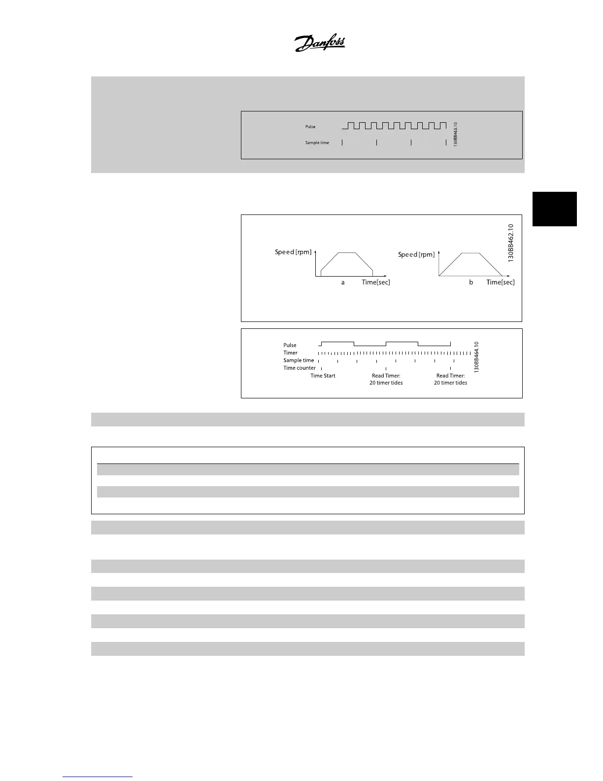
[31] Pulse edge triggered Edge-triggered pulse input counts number of pulse flanks per sample time. This gives a higher
resolution at high frequencies, but is not as precise at lower frequencies. Use this pulse principle
for encoders with very low resolution (e.g., 30 ppr).
[32] Pulse time based Time-based pulse input measures the duration between flanks. This gives a higher resolution at
lower frequencies, but is not as precise at higher frequencies. This principle has a cut-off frequency
which makes it unsuited for encoders with very low resolutions (e.g., 30 ppr) at low speeds.
a: very low encoder resolution b: standard encoder resolution
[34] Ramp bit 0 Enables a choice between one of the four ramps available, according to the table below.
[35] Ramp bit 1 Same as Ramp bit 0.
Preset ramp bit 10
Ramp 1 0 0
Ramp 2 01
Ramp 3 1 0
Ramp 4 11
[36] Line failure inverse Activates par. 14-10
Line Failure
. Line failure inverse is active in the logic "0" situation.
[41] Latched Precise Stop inverse Sends a latched stop signal when the precise stop function is activated in par. 1-83
Precise Stop
Function
. The latched precise stop inverse function is available for terminals 18 or 19.
[55] DigiPot Increase INCREASE signal to the digital potentiometer function described in par. group 3-9*
[56] DigiPot Decrease DECREASE signal to the digital potentiometer function described in par. group 3-9*
[57] DigiPot Clear Clears the digital potentiometer reference described in par. group 3-9*
[60] Counter A (Terminal 29 or 33 only) Input for increment counting in the SLC counter.
[61] Counter A (Terminal 29 or 33 only) Input for decrement counting in the SLC counter.
[62] Reset Counter A Input for reset of counter A.
[63] Counter B (Terminal 29 or 33 only) Input for increment counting in the SLC counter.
[64] Counter B (Terminal 29 or 33 only) Input for decrement counting in the SLC counter.
VLT
®
AutomationDrive FC 300 Instruction
Manual
4 How to Program
MG.33.AG.22 - VLT
®
is a registered Danfoss trademark
4-21
4
 Loading...


