3.2 Mechanical Installation
3.2.1 Mechanical Mounting
All Frame Sizes allow side-by-side installation except when a
IP21/IP4X/ TYPE 1 Enclosure Kit
is used (see the
Options and Accessories
section of the
Design Guide).
If the IP 21 Enclosure kit is used on frame size A1, A2 or A3, there must be a clearance between the drives of min. 50 mm.
For optimal cooling conditions allow a free air passage above and below the frequency converter. See table below.
Air passage for different frame sizes
Frame
size:
A1* A2 A3 A4 A5 B1 B2 B3 B4 C1 C2 C3 C4
a
(mm):
100 100 100 100 100 100 200 100 200 200 225 200 225
b
(mm):
100 100 100 100 100 100 200 100 200 200 225 200 225
* FC 301 only
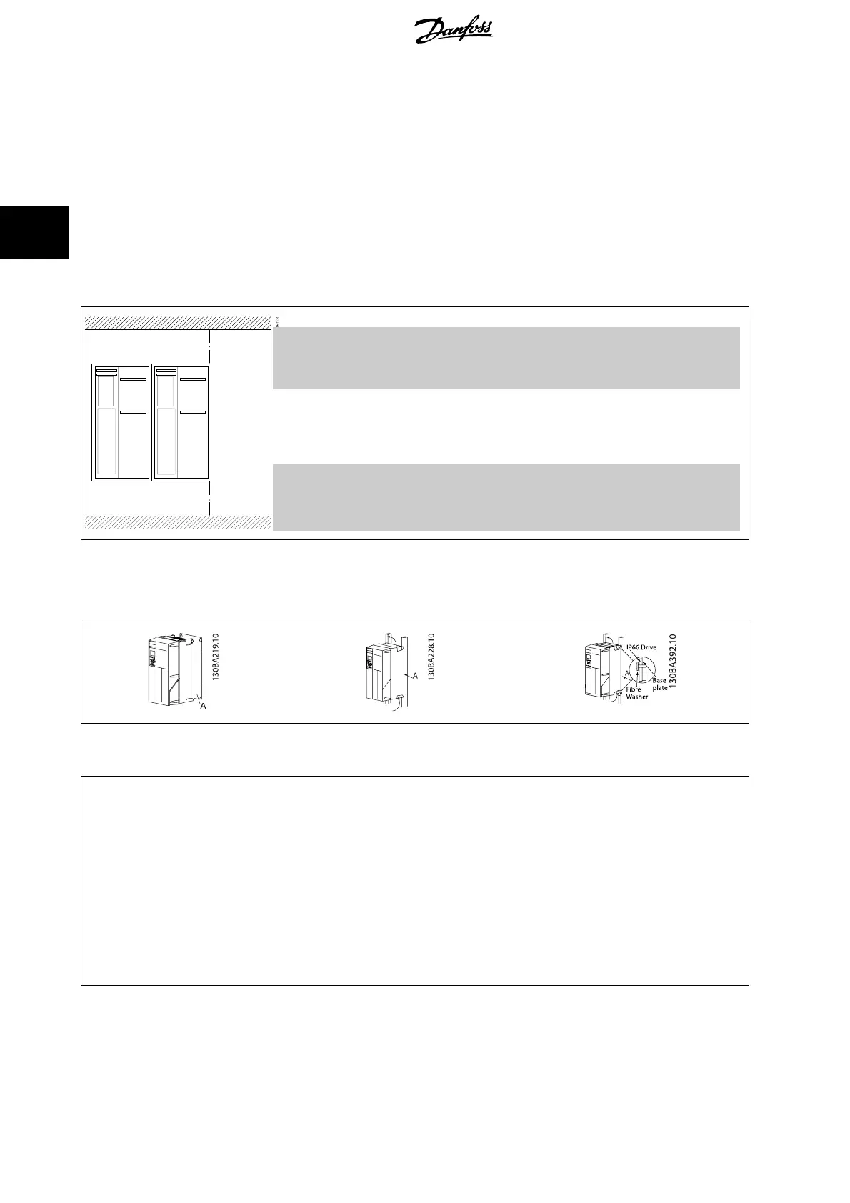
1. Drill holes in accordance with the measurements given.
2. You must provide screws suitable for the surface on which you want to mount the frequency converter. Retighten all four screws.
Table 3.1: Mounting frame sizes A4, A5, B1, B2, C1 andC2 on a non-solid back wall, the drive must be provided with a back plate A due to insufficient
cooling air over the heat sink.
Frame
Tightening torque for covers (Nm)
IP20 IP21 IP55 IP66
A1 * - - -
A2 * * - -
A3 * * - -
A4/A5 - - 2 2
B1 - * 2,2 2,2
B2 - * 2,2 2,2
B3 * - - -
B4 2 - - -
C1 - * 2,2 2,2
C2 - * 2,2 2,2
C3 2 - - -
C4 2 - - -
* = No screws to tighten
- = Does not exist
3 How to Install
VLT
®
AutomationDrive FC 300 Operating
Instructions
18
MG.33.AG.02 - VLT
®
is a registered Danfoss trademark
3

 Loading...


