3.3.4 Motor Connection
NB!
To comply with EMC emission specifications, screened/armoured cables are recommended. If an unscreened/unarmoured cable is
used, see section
Power and Control Wiring for Unscreened Cables
.. For more information, see
EMC Test Results
in the Design Guide.
See section General Specifications for correct dimensioning of motor cable cross-section and length.
Screening of cables: Avoid installation with twisted screen ends (pigtails). They spoil the screening effect at higher frequencies. If it is necessary to
break the screen to install a motor isolator or motor contactor, the screen must be continued at the lowest possible HF impedance.
Connect the motor cable screen to both the decoupling plate of the frequency converter and to the metal housing of the motor.
Make the screen connections with the largest possible surface area (cable clamp). This is done by using the supplied installation devices in the frequency
converter.
If it is necessary to split the screen to install a motor isolator or motor relay, the screen must be continued with the lowest possible HF impedance.
Cable-length and cross-section: The frequency converter has been tested with a given length of cable and a given cross-section of that cable. If the
cross-section is increased, the cable capacitance - and thus the leakage current - may increase, and the cable length must be reduced correspondingly.
Keep the motor cable as short as possible to reduce the noise level and leakage currents.
Switching frequency: When frequency converters are used together with Sine-wave filters to reduce the acoustic noise from a motor, the switching
frequency must be set according to the Sine-wave filter instruction in par. 14-01
Switching Frequency
.
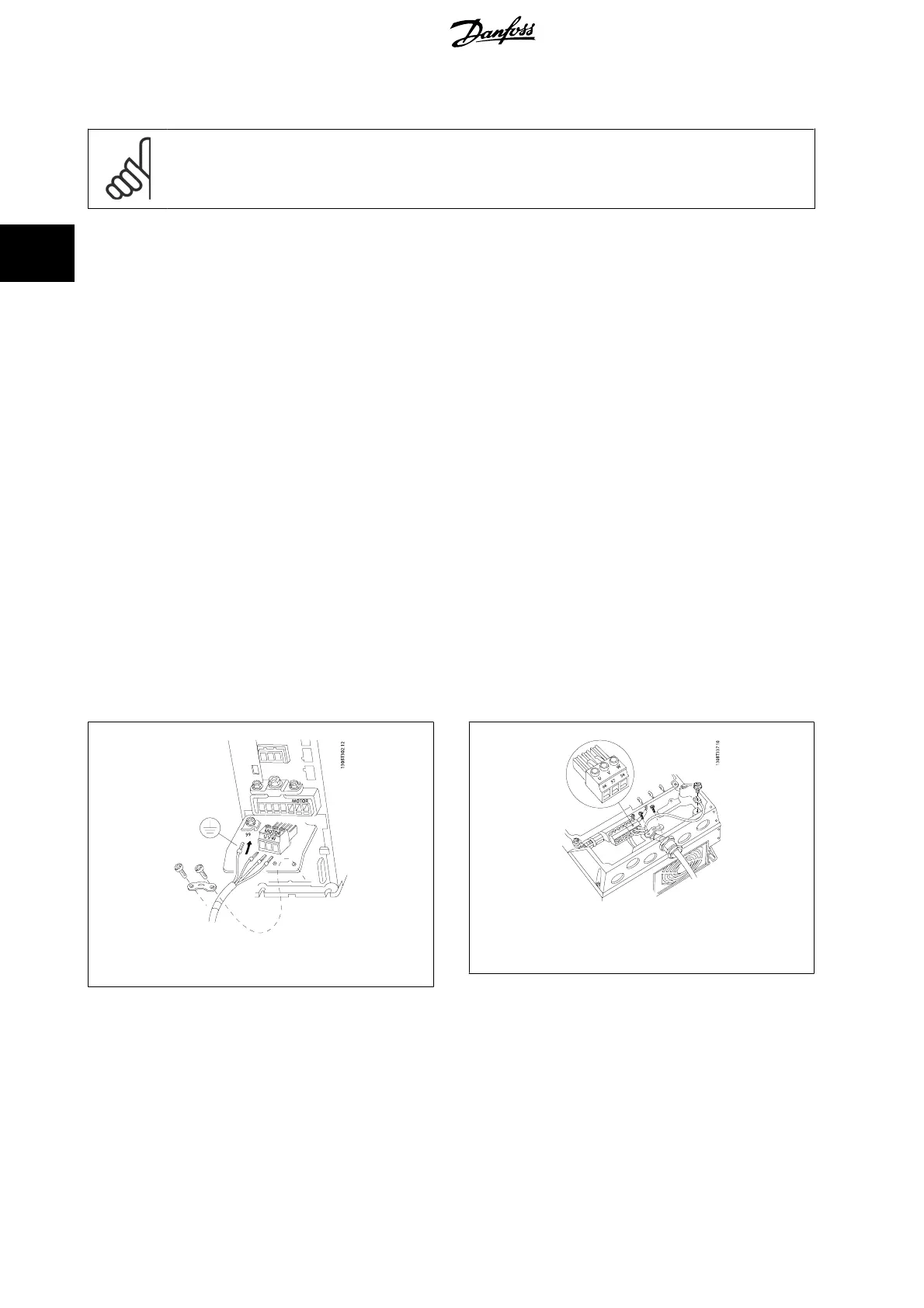
1. Fasten decoupling plate to the bottom of the frequency converter with screws and washers from the accessory bag.
2. Attach motor cable to terminals 96 (U), 97 (V), 98 (W).
3. Connect to earth connection (terminal 99) on decoupling plate with screws from the accessory bag.
4. Insert plug connectors 96 (U), 97 (V), 98 (W) (up to 7.5 kW) and motor cable to terminals labelled MOTOR.
5. Fasten screened cable to decoupling plate with screws and washers from the accessory bag.
All types of three-phase asynchronous standard motors can be connected to the frequency converter. Normally, small motors are star-connected (230/400
V, Y). Large motors are normally delta-connected (400/690 V, Δ). Refer to the motor name plate for correct connection mode and voltage.
Illustration 3.9: Motor connection for A1, A2 and A3
Illustration 3.10: Motor connection for size A4/A5 (IP 55/66/
NEMA Type 12)
3 How to Install
VLT
®
AutomationDrive FC 300 Operating
Instructions
26
MG.33.AG.02 - VLT
®
is a registered Danfoss trademark
3

 Loading...


