Airflow
The necessary airflow over the heatsink must be ensured. The flow rate is shown in Table 3.1.
Enclosure protection Frame size
Door fan/top fan airflow
Total airflow of multiple fans
Heatsink fan
Total airflow for multiple fans
IP21/NEMA 1
IP54/NEMA 12
D13
(LHD120)
3 door fans, 510 m
3
/h (300 cfm)
(2+1, 3x170=510)
2 heatsink fans, 1530 m
3
/h
(900 cfm)
(1+1, 2x765=1530)
E9 P315-P400
(LHD210)
4 door fans, 680 m
3
/h (400 cfm)
(2+2, 4x170=680)
2 heatsink fans, 2675 m
3
/h
(1574 cfm)
(1+1, 1230+1445=2675)
F18
(LHD330)
6 door fans, 3150 m
3
/h
(1854 cfm)
(6x525=3150)
5 heatsink fans, 4485 m
3
/h
(2639 cfm)
2+1+2, ((2x765)+(3x985)=4485)
Table 3.1 Heatsink Air Flow
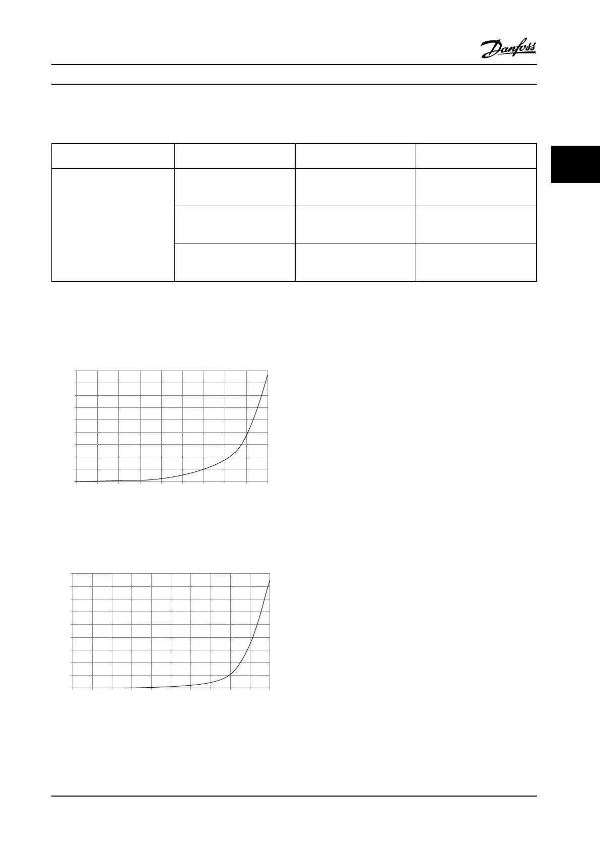
External ducts
If additional duct work is added externally to the Rittal cabinet, the pressure drop in the ducting must be calculated. Use
the charts below to derate the adjustable frequency drive according to the pressure drop.
90
80
70
60
50
40
30
20
10
0
0 0.5 4.9 13 27.3 45.9 66 89.3 115.7 147
(%)
(Pa)
Pressure Increase
Drive Derating
130BB007.10
Figure 3.1 D-Frame Derating vs. Pressure Change
Drive Air Flow: 450 cfm (765 m
3
/h)
90
80
70
60
50
40
30
20
10
0
(%)
Drive Derating
0 0 0.1 3.6 9.8 21.5 43.4 76 237.5 278.9
(Pa)
Pressure Change
130BB010.10
147.1
Figure 3.2 E-Frame Derating vs. Pressure Change (Small Fan), P315
Drive Air Flow: 650 cfm (1105 m
3
/h)
Installation Instruction Manual
MG37A222 Danfoss A/S © Rev. 2014-02-07 All rights reserved. 17
3 3

 Loading...


