3.4.19 Electrical Installation, Control
Terminals
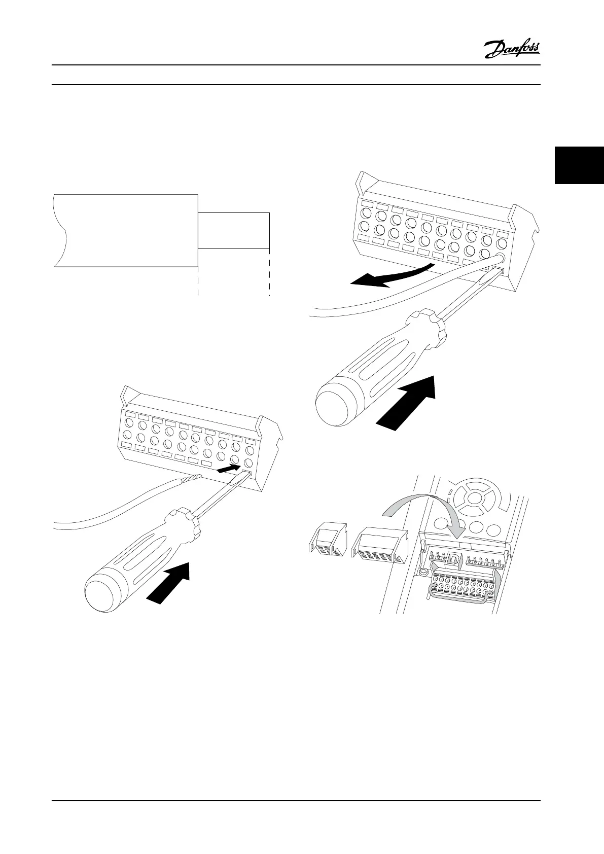
To connect the cable to the terminal:
1. Strip insulation by about 0.35–0.4 in [9–10 mm]
Electrical installationControl terminals
130BA150.10
9 - 10 mm
(0.37 in)
Figure 3.22 Length to Strip the Insulation
2. Insert a screwdriver (max. 0.016x0.1 in [0.4x2.5
mm]) in the square hole.
3. Insert the cable in the adjacent circular hole.
Figure 3.23 Inserting the Cable in the Terminal Block
4. Remove the screwdriver. The cable is now
mounted in the terminal.
To remove the cable from the terminal:
1. Insert a screwdriver (max. 0.016x0.1 in [0.4x2.5
mm]) in the square hole.
2. Pull out the cable.
Figure 3.24 Removing the Screwdriver after Cable Insertion
Figure 3.25 Control Terminal Locations
Installation Instruction Manual
MG37A222 Danfoss A/S © Rev. 2014-02-07 All rights reserved. 33
3 3

 Loading...


