3.3.5 Terminal Locations - Frame Size F18
Take the position of the terminals into consideration when designing the cable access.
F-frame units have four interlocked cabinets:
1. Input options cabinet (not optional for LHD)
2. Filter cabinet
3. Rectifier cabinet
4. Inverter cabinet
See chapter 2.1 Exploded View Drawings for exploded views of each cabinet. Line power inputs are located in the input
option cabinet, which conducts power to the rectifier via interconnecting bus bars. Output from the unit is from the inverter
cabinet. No connection terminals are located in the rectifier cabinet. Interconnecting bus bars are not shown.
1 2 3
4
0.0[0.00]
76.4[3.01]
128.4[5.05]
119.0[4.69]
171.0[6.73]
294.6[11.60]
344.0[13.54]
3639[14.33]
438.9[17.28]
75.3[2.96]
150.3[5.92]
154.0[6.06]
219.6[18.65]
0.0[0.00]
244.4[9.62]
244.4[1.75]
939.0[36.97]
1031.4[40.61]
0.0[0.00]
134.6[5.30]
130BA851.12
0.0[1.75]
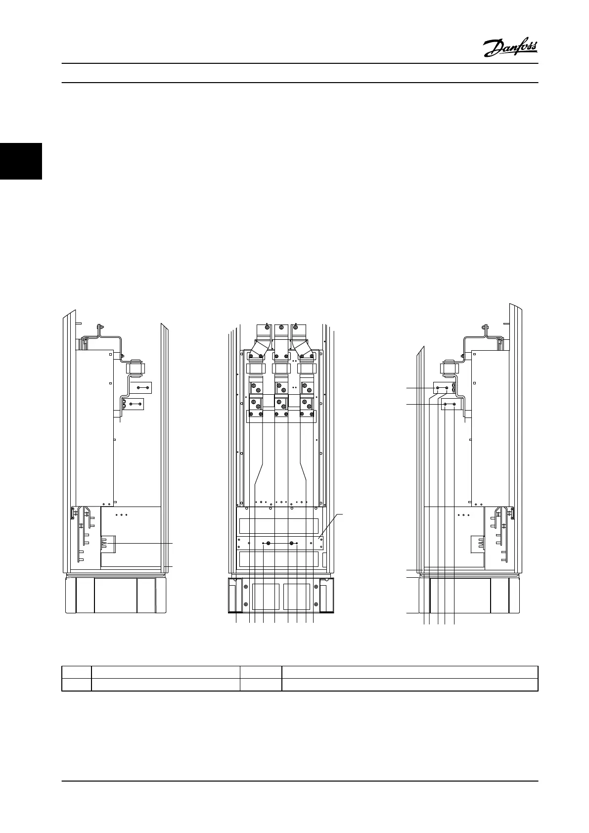
1 Right side cutaway 3 Left side cutaway
2 Front view 4 Ground bar
Figure 3.10 Frame Size F18 Input Option Cabinet - Fuses Only
The connector plate is 1.65 in [42 mm] below .0 level. Shown are the left side view, front, and right.
Installation
Instruction Manual
22 Danfoss A/S © Rev. 2014-02-07 All rights reserved. MG37A222
33

 Loading...


