130BA849.13
.0 [.0]
54.4[2.1]
169.4 [6.7]
284.4 [11.2]
407.3 [16.0]
522.3 [20.6]
637.3 [25.1]
287.4 [11.3]
253.1 [10.0]
.0 [.0]
.0 [.0]
339.4 [13.4]
287.4 [11.3]
.0 [.0]
339.4 [13.4]
308.3 [12.1]
465.6 [18.3]
465.6 [18.3]
198.1[7.8]
234.1 [9.2]
282.1 [11.1]
318.1 [12.5]
551.0 [21.7]
587.0 [23.1]
635.0 [25.0]
671.0 [26.4]
44.40 [1.75]
244.40 [9.62]
204.1 [8.0]
497.1 [19.6]
572.1 [22.5]
180.3 [7.1]
129.1 [5.1]
4
6
4
1
2
3
5
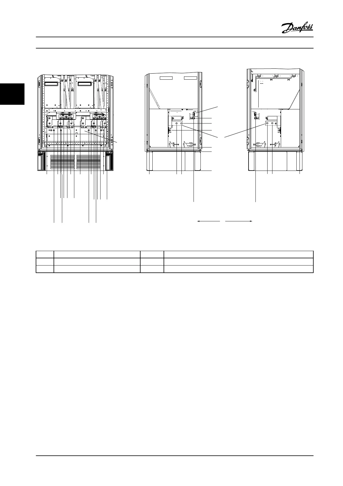
1 Front View 4 Brake Terminals
2 Left Side View 5 Ground bar
3 Right Side View
Figure 3.12 Frame Size F18 Inverter Cabinet
The connector plate is 1.65 in [42 mm] below .0 level. Shown are the left side view, front, and right.
Installation Instruction Manual
24 Danfoss A/S © Rev. 2014-02-07 All rights reserved. MG37A222
33

 Loading...


