FC 300 Design Guide
How to Read this Design Guide
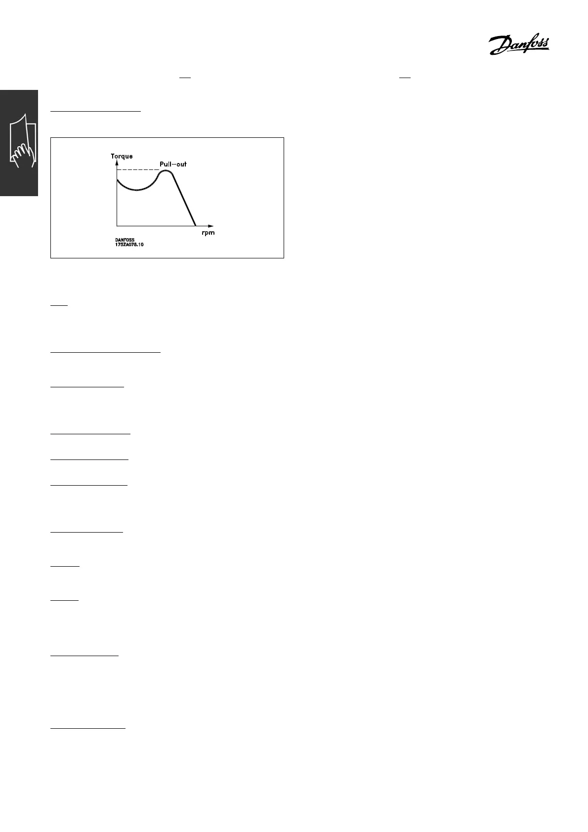
Break-away torque:
η
VLT
The efficiency of the adjustable frequency drive is defined as the ratio between
the power output and the power input.
S
tart-disabl e command:
A stop command belonging to the g
roup 1 control commands - see this group.
S
top co mmand:
See C ontrol comma n ds.
References:
A
nalog Reference
A signal transmitted to the an
alog inputs 53 or 54, can be voltage or current.
B
inary Reference
A signal transmitted to the serial communication port.
P
reset Reference
A defined preset reference to be set from -100% to +100% of the reference range. Sele ction
of eight prese t references via the digital terminals.
P
ulse Reference
A signal t ransmitted to t h
e digital inputs (terminal 29 or 33).
R
ef
MAX
The maximum reference signalvalue. Setinpar. 3-03.
R
ef
MIN
The minimum reference signal value. Set in par. 3-02.
Miscellaneous:
A
nalog Inputs:
The anal
og inputs are u sed for controlling various functions of the adjustable frequency drive.
There are two types of analog inputs:
Current inp u t, 0-20 mA
Voltage i
nput, 0-10 V DC.
A
nalog O
utputs:
The analog outputs ca n supply a signal of 0-20 m A, 4-20 mA, or a digital signal.
10
MG.33.B3.22 - VLT is a registered Danfoss trademark
 Loading...


