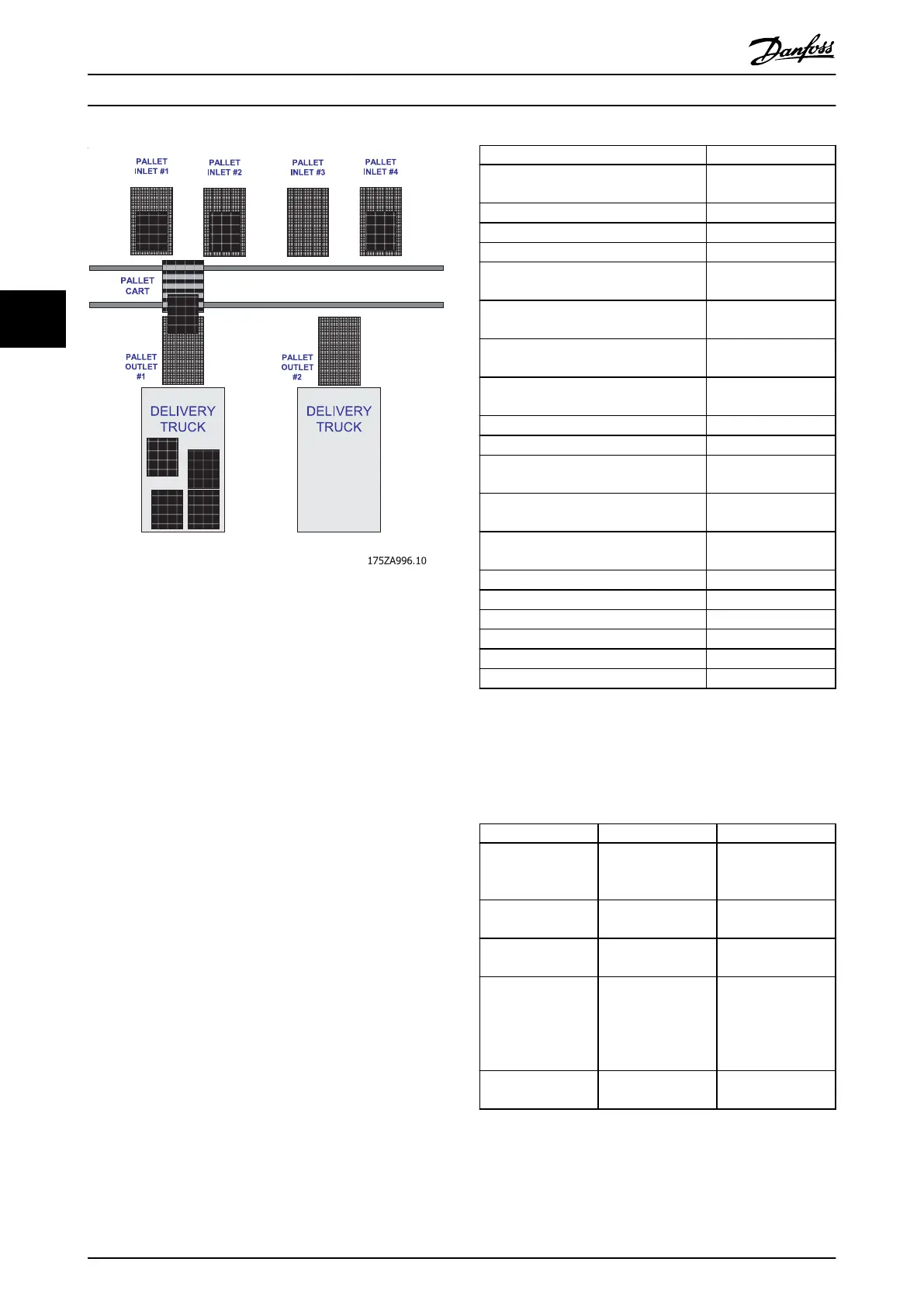
Illustration 4.1 Pallet Conveyor System (Example)
A typical work process is:
1. Moves the (empty) pallet conveyor cart to pallet
inlet no. 1 to pick up a loaded pallet.
2. Waits until the pallet is successfully transferred to
the cart.
3. Moves to pallet outlet no. 2.
4. Waits until the pallet is successfully transferred to
the outlet conveyor and so on.
4.6.2
Electrical Connection
Use encoder to MCB102 as feedback source.
Use digital inputs 18 and 19 to specify the index of the
preset position.
Mark 0 position and connect the home switch to digital
input 31.
4.6.3
Settings
Set the parameters as described in the table below.
Parameter Value
5-10 Terminal 18 Digital Input
[160] Go To Target
Pos
5-11 Terminal 19 Digital Input
[162] Pos. Idx Bit0
5-12 Terminal 27 Digital Input
[163] Pos. Idx Bit1
5-13 Terminal 29 Digital Input
[150] Go To Home
5-16 Terminal 31 Digital Input
[151] Home Ref.
Switch
Parameter 5-40 Function Relay
Array element 0: Array
element 1:
Parameter 6-92 Terminal 42 Digital Output
[170] Homing
Completed
Parameter 6-72 Terminal 45 Digital Output
[171] Target Position
Reached
Parameter 33-41 Negative Software Limit
*-500,000 UU
Parameter 33-42 Positive Software Limit
*500,000 UU
Parameter 33-43 Negative Software Limit
Active
[0] *Inactive
Parameter 33-44 Positive Software Limit
Active
[0] *Inactive
Parameter 32-80 Maximum Allowed
Velocity
*1,500 RPM
Parameter 37-17 Pos. Ctrl Fault Behaviour
[0] *Ramp Down Brake
Parameter 37-07 Pos. Auto Brake Ctrl
[0] Disable
Parameter 37-08 Pos. Hold Delay
*0
Parameter 37-09 Pos. Coast Delay
*200 ms
Parameter 37-10 Pos. Brake Delay
*200 ms
Parameter 37-11 Pos. Brake Wear Limit
*0
Table 4.4 Parameter Set-up
4.6.4
Homing
Set the parameters for homing as described in Table 4.5.
Parameter Value Description
Parameter 33-00 Ho
ming Mode
[1] Forced Manual
Mode
Must complete
homing before
positioning.
Parameter 33-01 Ho
me Offset
*0
Parameter 33-02 Ho
me Ramp Time
*10ms
Parameter 33-03 Ho
ming Velocity
-100 RPM Assume the
beginning position
is positive, then the
homing velocity
should be negative
Parameter 33-04 Ho
ming Behaviour
[1] *Reverse no
index
Table 4.5 Homing Set-up
Perform the homing process as follows:
Positioning Control
VLT
®
AutomationDrive FC 360
18 Danfoss A/S © 11/2014 All rights reserved. MG06E102
44

 Loading...


