1.
Select Auto On mode via LCP/GLCP.
2. Switch on digital input 29 to start homing. The
motor will rotate and move the conveyor cart to
the home position.
3. Wait until digital out 42 is changed to high level.
4. Swtich off digital input 29 to stop homing.
4.6.5 Positioning
Set the parameters for positioning as described in
Table 4.6.
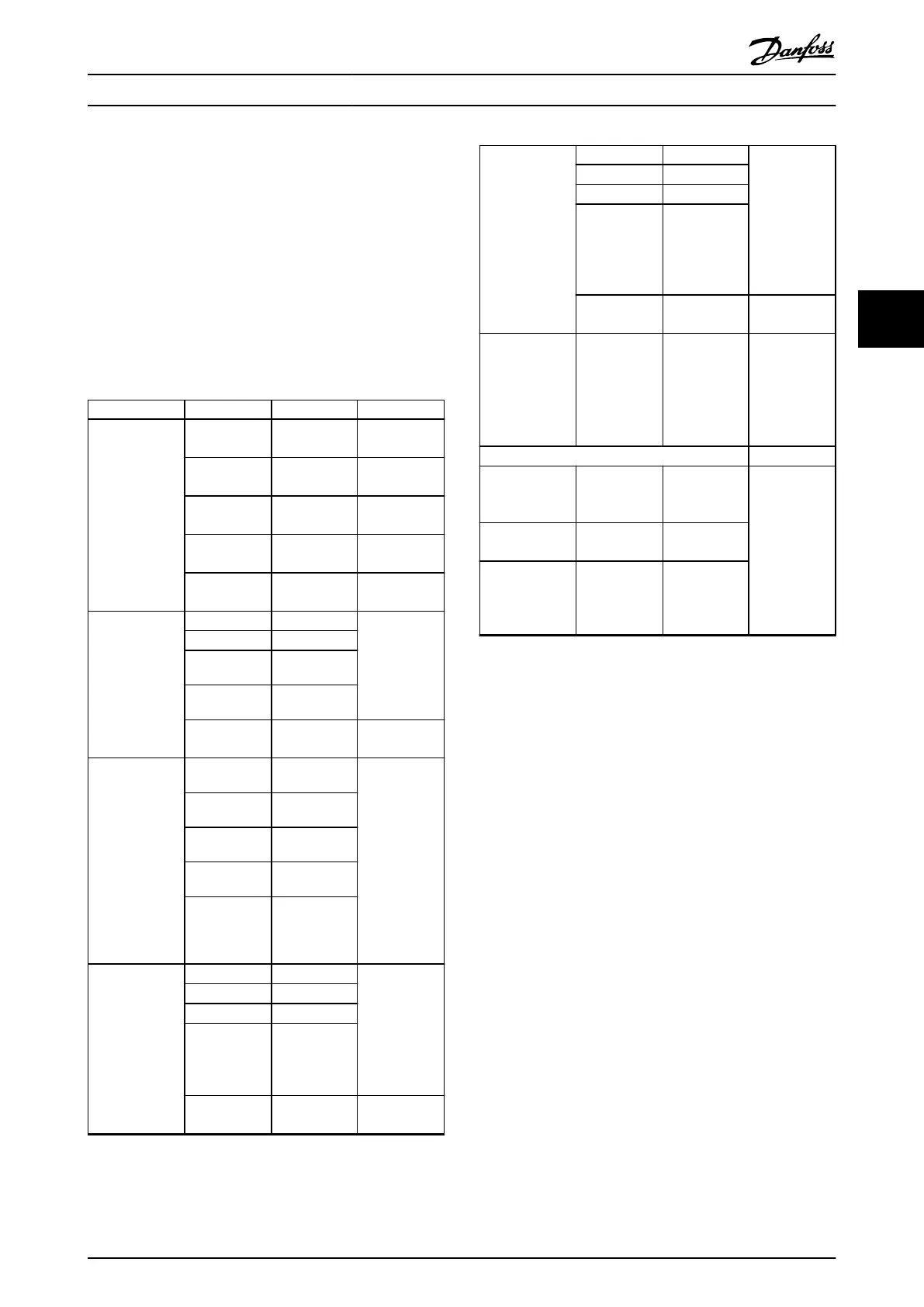
Parameter Array Index Value Description
Parameter 37-02
Pos. Target
0 5800 UU Position 0,
inlet 1.
1 3800 UU Position 1,
inlet 2.
2 1800 UU Position 2,
inlet 3.
3 2300 UU Position 3,
outlet.
4–7 *0 UU Not used in
this example.
Parameter 37-03
Pos. Type
0 *[0] Absolute
1 *[0] Absolute
2 *[0] Absolute
3 *[0] Absolute
4–7 *[0] Absolute Not used in
this example.
Parameter 37-04
Pos. Velocity
0 300 RPM The cart is full
to outlet, but
empty to inlet.
It means the
load to Pos3 is
larger than to
Pos0/1/2. So
we set Pos3’s
velocity to be
a little lower
than others.
1 300 RPM
2 300 RPM
3 120 RPM
4-7 *100 RPM
Parameter 37-05
Pos. Ramp Up
Time
0 1000 ms Considering
the velocity
setting, set the
ramp-up time
of position 3
to be
relatively long.
1 1000 ms
2 1000 ms
3 2000 ms
4-7 *5000 ms Not used in
this case.
Parameter 37-06
Pos. Ramp Down
Time
0 1000 ms Considering
the velocity
settings, set
the ramp-
down time of
position 3 to
be relatively
long.
1 1000 ms
2 1000 ms
3 2000 ms
4–7 *5000 ms Not used in
this example.
Parameter 33-47
Target Position
Window
– 20 UU Set to a value
based on the
actual
situation of
the
application.
PID Settings
7-33 Process PID
Proportional
Gain
– 0.5 These are only
empirical
settings,
should be
adjusted
following the
situation of
commissioning
in real system.
7-34 Process PID
Integral Time
– 20
7-35 Process PID
Differentiation
Time
– 0
Table 4.6 Positioning Parameter Set-up
Operating procedure of positioning
Go to position 0 to get a pallet:
1. Switch off digital inputs 19 and 27 to select
position 0.
2. Swith on digital 18 to move to position 0.
3. Wait until digital out 42 is turned on, which
means the target position is reached. Make sure
the pallet transfer starts after the position is
reached. Otherwise, adjust the system or
parameters.
4. Switch off digital input 18 to stop positioning.
5. Wait until the pallet is transferred to the cart.
Go to position 1 to get a pallet:
1. Switch on digital input 19 and switch off digital
input 27 to select position 1.
2. Swith on digital 18 to move to position 1.
3. Wait until digital out 42 is turned on, which
means the target position is reached. Make sure
the pallet transfer starts after the position is
reached. Otherwise, adjust the system or
parameters.
4. Switch off digital input 18 to stop positioning.
5. Wait until the pallet is transferred to the cart.
Positioning Control
Application Guide
MG06E102 Danfoss A/S © 11/2014 All rights reserved. 19
4 4

 Loading...


