7.6.3 Motor Insulation
For motor cable lengths that are less than or equal to the
maximum cable length listed in chapter 5.5 Cable Speci-
cations, use the motor insulation ratings shown in
Table 7.10. If a motor has lower insulation rating, Danfoss
recommends using a dU/dt or sine-wave lter.
Nominal mains voltage Motor insulation
U
N
≤420 V
Standard U
LL
=1300 V
420 V<U
N
≤500 V
Reinforced U
LL
=1600 V
500 V<U
N
≤600 V
Reinforced U
LL
=1800 V
600 V<U
N
≤690 V
Reinforced U
LL
=2000 V
Table 7.10 Motor Insulation Ratings
7.6.4 Motor Bearing Currents
To eliminate circulating bearing currents in all motors
installed with the drive, install NDE (non-drive end)
insulated bearings. To minimize DE (drive end) bearing and
shaft currents, ensure proper grounding of the drive,
motor, driven machine, and motor to the driven machine.
Standard mitigation strategies:
•
Use an insulated bearing.
•
Follow proper installation procedures.
- Ensure that the motor and load motor
are aligned.
- Follow the EMC Installation guideline.
- Reinforce the PE so the high-frequency
impedance is lower in the PE than the
input power leads.
- Provide a good high-frequency
connection between the motor and the
drive. Use a shielded cable that has a
360° connection in the motor and the
drive.
- Ensure that the impedance from the
drive to building ground is lower than
the grounding impedance of the
machine. This procedure can be dicult
for pumps.
- Make a direct ground connection
between the motor and load motor.
•
Lower the IGBT switching frequency.
•
Modify the inverter waveform, 60° AVM vs.
SFAVM.
•
Install a shaft grounding system or use an
isolating coupling.
•
Apply conductive lubrication.
•
Use minimum speed settings if possible.
•
Try to ensure that the mains voltage is balanced
to ground. This procedure can be dicult for IT,
TT, TN-CS, or grounded leg systems.
•
Use a dU/dt or sine-wave lter.
7.7 Residual Current Devices (RCD) and
Insulation Resistance Monitor (IRM)
Use RCD relays, multiple protective grounding, or
grounding as extra protection, provided they comply with
local safety regulations.
If a ground fault appears, a DC current can develop in the
faulty current. If RCD relays are used, local regulations
must be observed. Relays must be suitable for protection
of 3-phase equipment with a bridge rectier and for a brief
discharge on power-up. See chapter 7.8 Leakage Current for
more details.
7.8 Leakage Current
Follow national and local codes regarding protective
grounding of equipment where leakage current exceeds
3.5 mA.
Drive technology implies high-frequency switching at high
power. This high-frequency switching generates a leakage
current in the ground connection.
The ground leakage current is made up of several contri-
butions and depends on various system
congurations,
including:
•
RFI ltering.
•
Motor cable length.
•
Motor cable shielding.
•
Drive power.
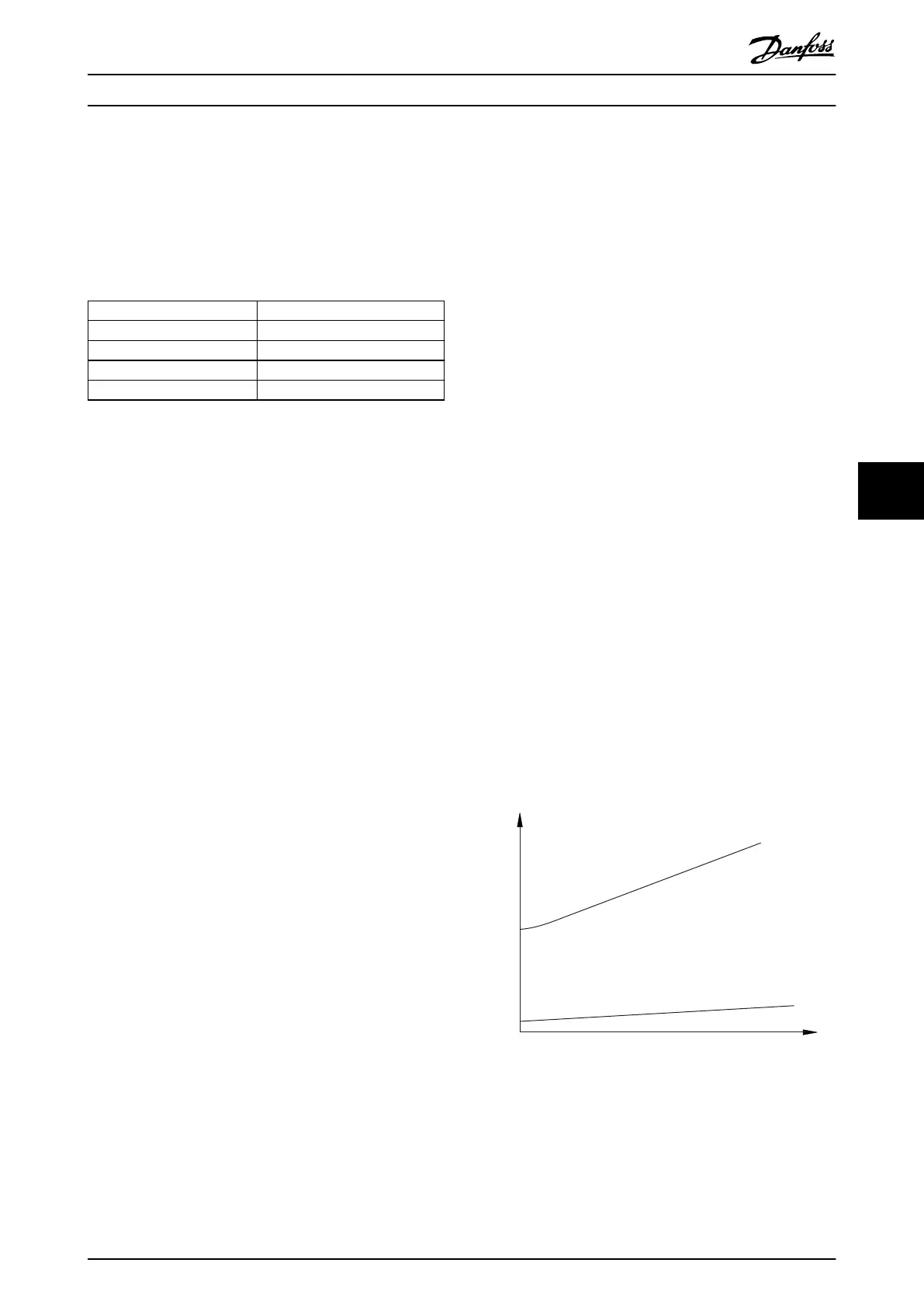
130BB955.12
a
b
Leakage current
Motor cable length
Illustration 7.11 Motor Cable Length and Power Size Inuence
the Leakage Current. Power Size a > Power Size b.
The leakage current also depends on the line distortion.
Electrical Installation Con... Design Guide
MG06K102 Danfoss A/S © 03/2019 All rights reserved. 47
7 7
 Loading...


